
Self-Tapping Screws: Choose the Type, Hole and Tightening Method
Choose self-tapping screws for sheet-metal joints, match the pilot hole to the screw type, and check seating without stripping the parent material.
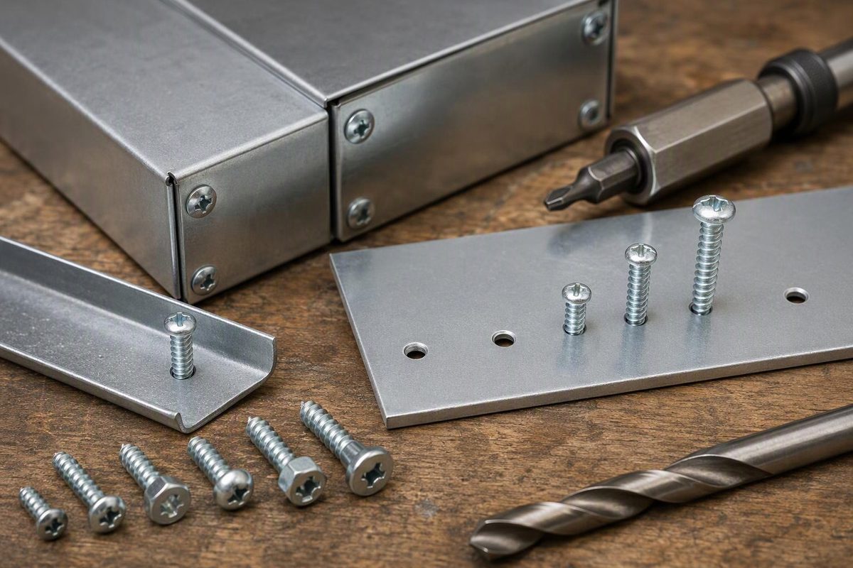
Self-tapping screws make their own mating thread; they do not necessarily make their own hole. For a garage-built sheet-metal cover or light bracket, start with the screw’s full specification, the material it will thread into and that material’s thickness. A sharp point alone does not tell you which drill to use.
This guide covers light-duty sheet-metal joints. Do not treat ordinary sheet-metal screws as substitutes for specified structural fasteners: Bossard’s construction guidance says they are not intended to transfer high forces and provides no reference preload values for them.
Identify what the screw actually does
Three descriptions answer different questions:
| Description | What happens during installation | What to check |
|---|---|---|
| Thread-forming | The screw displaces material to form the mating thread | Suitable parent material and specified pilot-hole geometry |
| Thread-cutting | Cutting edges remove material to form the thread | Specified pilot hole and room for the resulting chips |
| Self-drilling | A drill-like point makes the hole before the threads engage | Rated drilling capacity, material and point length |
SFS distinguishes thread-forming from thread-cutting screws, while Tanner explains the drill-point requirements. A self-drilling screw also forms or cuts its mating thread, but not every self-tapper is self-drilling. Its unthreaded drill point must be long enough to drill through the material before the threads engage; early engagement can bend or break the screw.
Before ordering, record the screw type, diameter, pitch or threads per inch, length, head, drive, material and finish. Also record the cover thickness, receiving-sheet thickness and available space behind the joint. Match these to the supplier’s application data—including minimum material thickness and required thread engagement—not merely to another screw that looks similar.
Choose the pilot hole by screw type
There is no universal “self-tapping screw drill size.” SFS states that pilot-hole size affects installation performance and pull-out strength, and directs users to product data for the fastener and substrate thickness.
For a limited inch-size reference, these entries agree in the TR Fastenings Type AB chart and Fastener SuperStore’s pilot-hole guide:
| Type AB screw | Nominal drill diameter | Number drill |
|---|---|---|
| #6-20 | 0.1160 in. | #32 |
| #8-18 | 0.1360 in. | #29 |
| #10-16 | 0.1590 in. | #21 |
These are reference selections, not approval for every material. TR limits its values to case-hardened steel self-tappers in a simple joint with clearance holes, under its stated tightening conditions; other screws or sheet materials require trials. The actual screw manufacturer’s recommendation takes priority.
A #8-18 Type AB screw is not an #8-32 machine-thread screw. Do not borrow a cutting-tap drill chart simply because the nominal screw number matches. Use the drill-bit diameter chart to identify the specified bit, not to substitute the nearest convenient fraction without checking the permitted hole range.
The drill marking is a nominal tool diameter. The finished hole still needs checking for oversize, ovality and burrs.
Drill, assemble and inspect
For a simple cover-to-base joint in which only the base receives the thread:
- Make a representative trial joint. Use offcuts matching both materials and thicknesses, the intended screw and the same drilling method. A different scrap thickness does not verify the final joint.
- Mark and clamp the parts. Check alignment, driver access and clearance behind the screw point. Keep wiring and other components out of its path.
- Make the two hole functions distinct. Give the cover the specified clearance hole and the receiving sheet its specified pilot hole. Bossard illustrates this arrangement separately from joints where both sheets engage the screw.
- Remove chips and burrs. Keep the mating faces flat. Do not turn light deburring into a deep countersink that removes useful thread-bearing material.
- Drive square to the surface. Use a correctly fitting bit and controlled rotation. Follow any specified installation speed and tightening torque.
- Inspect the seated joint. The head should bear properly, the parts should meet without an unintended gap, and the sheet should not be distorted. If the screw spins without tightening, stop; additional turns will not restore the damaged thread.
Tightening resistance is not clamp force
During installation, some torque is spent making the thread. Resistance before the head reaches the work is therefore not evidence that the parts are clamped. For example, Bossard shows thread formation and final tightening as separate stages for SHEETtracs screws in its assembly guidance.
Do not apply a general bolt-torque table to this joint. Use the fastener’s application-specific setting and a suitable controlled tool where torque is specified. Do not use an undocumented drill-clutch setting as a torque specification.
A clean trial installation checks assembly behaviour; it does not establish load capacity or fatigue life. If the cover will be removed frequently, or the receiving sheet already has stripped holes, consider a machine screw with a nut or a suitable threaded insert for metal rather than repeatedly working the same sheet-metal thread.