
Which Thread Insert for Metal?
Selection is governed by how the insert fits the hole, parent metal, fastener, access condition, tooling and service load in the actual application.
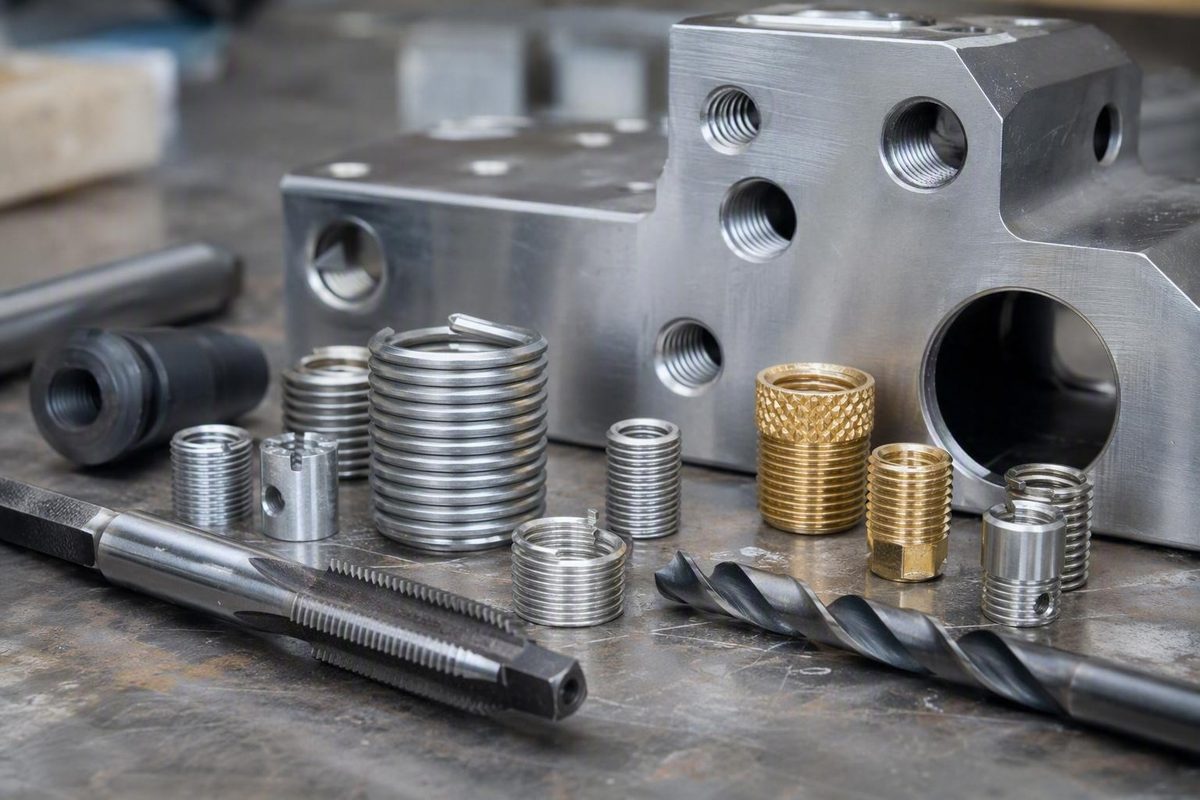
Thread inserts for metal solve several different problems, but they do not solve them in the same way. A formed-wire coil used to restore a stripped hole in an aluminum casting is not interchangeable with a rivet nut installed in sheet metal, and neither is automatically an acceptable substitute for a mechanically locked solid insert.
The useful question is not, “Which insert is strongest?” It is, “Which insert fits this hole, parent metal, fastener, access condition, tooling, and service load?”
Before ordering, determine whether the job is thread repair, reinforcement, or thin-sheet fastening. Then measure the part, identify the service conditions, and obtain the current drawing and installation instructions for the exact insert. This article provides a selection framework and general workflow—not universal drill sizes, torque values, inspection limits, or approval for a particular repair.
Start With the Job: Repair, Reinforcement, or Thin-Sheet Fastening?
A threaded insert is a component installed in a workpiece to provide an internal thread for a screw or stud. Depending on its design, it may be threaded, pressed, swaged, riveted, keyed, or otherwise retained in the parent material.
Start by routing the job into one of three categories:
- Damaged thread in substantial metal: Evaluate helical, solid-wall, or key-locking repair systems.
- New or serviceable thread in soft metal: Evaluate inserts intended to reduce wear from repeated assembly.
- Thin material or access from only one side: Evaluate rivet nuts, captive nuts, cage nuts, or clip-on nuts rather than assuming a drill-and-tap repair will work.
These categories can overlap. A solid insert might repair a stripped hole while also producing a more serviceable thread. A coil may be installed in an undamaged aluminum part during initial manufacture. The distinction still matters because it directs attention to the appropriate geometry, retention method, and tooling.
Thread repair normally removes the damaged internal thread and prepares a larger hole for an insert that recreates the internal diameter and pitch required by the original fastener. Many systems therefore preserve the original bolt size rather than requiring the entire assembly to accept the next nominal fastener size. Repair kits commonly include inserts, a tap, and an insertion tool, although a drill and tap wrench may be separate. E-Z LOK’s repair-kit guide documents that original-thread-size approach and its typical kit contents.
Thread reinforcement begins before—or independently of—failure. A builder may install an insert in a new aluminum housing because the fastener will be removed repeatedly. Selection then depends on factors such as available engagement, resistance to axial extraction and rotation, service environment, and the manufacturer’s base-material requirements.
Thin-sheet fastening is different. Sheet may not provide enough thickness for useful direct thread engagement. A rivet nut adds an internal thread from one accessible side, while captive, cage, and clip-on nuts place a separate threaded element at the panel. These systems rely on deformation, pressing, swaging, clipping, or mechanical capture rather than a long external thread cut into a thick casting.
Inserts can also support a change between unified and metric internal threads, but the desired inside thread is only half the selection. The insert’s exterior still must fit the available hole, wall thickness, edge distance, mating-part clearance, and installation method. General descriptions of threaded inserts cover repair, reinforcement, thin-material fastening, and thread-system conversion, but they do not supply the component-specific dimensions needed to approve a conversion. This overview distinguishes those principal uses and insert families.
Do not use this article as a drill-size chart. The required drill, tap, counterbore, depth, seating position, and completion operation depend on the exact insert. Whether the finished component is suitable for service depends on the component and application—not merely on whether an insert can physically be installed.
Thread Insert Types Compared
The main insert families differ in construction, preparation, retention, access, and removability. This table is a routing aid, not a substitute for a product drawing.
| Insert family | Typical task | Parent-material requirement | Hole enlargement | Common tooling configuration | Rear access | Retention method | Removal considerations |
|---|---|---|---|---|---|---|---|
| Helical coil | Repair or reinforce threads in substantial metal | Enough material for the specified insert thread and installed length | Often relatively limited | Specified drill, STI tap, insertion tool, and tang tool when applicable | Usually not required | Coil engagement in an insert-specific tapped thread | Extraction is product-dependent and may damage the prepared thread |
| Solid-wall, externally threaded | Repair or create reusable threads | Enough wall, edge distance, and depth for the body | Commonly greater than for a comparable coil | Specified drill, external-thread tap, and driver; some systems add adhesive or other operations | Usually not required | External thread, adhesive, flange, friction, or another product-specific feature | Procedure depends on the retention system |
| Key- or pin-locking solid insert | Repair where rotational retention is important | Enough material for the body and locking features | Commonly substantial | Drill, tap, driver, and specified key- or pin-setting operation | Usually not required | Keys, pins, or wedges mechanically engage the parent material | Removal may be destructive or enlarge the hole |
| Press-fit or swaged captive nut | Add a thread to a compatible panel | Panel and hole must satisfy the product requirements | Determined by the fastener design | Arbor press or other specified setting equipment for applicable designs | Depends on the design and assembly sequence | Pressing, swaging, displacement, or capture | Removal method and resulting panel condition are product-dependent |
| Rivet nut | Add an internal thread to thin material or a blind-access assembly | Panel must be within the specified material and thickness conditions | Hole sized for the rivet-nut body | Compatible setter, mandrel, and nosepiece | No | Tubular body deforms to clamp the panel | Damaged units may require destructive removal |
| Cage or clip-on nut | Provide a replaceable thread in sheet metal | Suitable edge, opening, or mounting geometry | Often little conventional hole preparation | Hand tools for applicable designs | Edge or opening access required | Spring clip or cage captures a separate nut | Often replaceable without machining a set insert from a round hole |
A helical insert is a coil of formed wire installed in a specially tapped hole. The fastener engages the coil’s internal thread. Because the body is formed from wire rather than a thick sleeve, many coil systems require less enlargement than solid-bodied alternatives. That can be useful near an edge, passage, gasket face, or thin wall, but only if the product drawing confirms adequate material.
A solid-wall insert is a one-piece sleeve with an internal fastener thread and an externally threaded or otherwise retained body. Its larger outside diameter can provide more engagement area, but it also removes more parent metal. That tradeoff may be acceptable in one casting and unsuitable in another.
A key- or pin-locking insert is generally a solid insert that is seated and then mechanically locked. KIPP, for example, describes reinforced steel and stainless-steel inserts secured against rotation by locking pins or wedges and installed with an assembly tool. Its larger-cross-section variant is described for higher-stress applications, but that description is not a load rating. KIPP’s product page illustrates this mechanically locked insert family.
Press-fit and swaged captive nuts are panel-oriented fasteners. They can be considered when a panel is too thin or weak to tap directly, provided the panel, hole, support, and setting process meet the exact product requirements. They should not be treated as generic parts that can simply be hammered into any convenient opening.
A rivet nut is a one-piece, internally threaded tubular rivet installed from one accessible side. During the specified setting operation, its body deforms to secure it to the panel. That makes the family a principal candidate for enclosed tubing, boxed structures, and panels whose rear face cannot be reached.
Cage and clip-on nuts are alternatives where an edge or mounting opening is accessible. The nut is held by a carrier instead of being permanently set into a round hole, which can simplify replacement when the panel geometry permits their use.
No insert family is categorically strongest. Outside diameter, installed length, thread engagement, parent-metal properties, edge distance, installation quality, loading direction, and failure mode all influence performance. A larger insert may appear superior in a comparison simply because it engages more parent material.
Measure the Part Before Choosing an Insert
Ordering by bolt size alone is a common selection error. The internal thread tells you which fastener fits; the exterior of the insert determines how much material must be removed and which tools are required.
Record the following before selecting a part number:
- Original fastener diameter
- Unified, metric, or other thread standard
- Thread pitch
- Fastener grade or property class, where relevant
- Current damaged-hole diameter and shape
- Usable hole depth, not merely the visible depth at the mouth
- Through-hole or blind-hole geometry
- Wall thickness around the hole
- Distance from the proposed prepared-hole edge to the component edge
- Distance to passages, bearing bores, dowel holes, gasket lands, and sealing faces
- Workpiece or panel thickness
- Space for the drill, tap wrench, counterbore, driver, or setting tool
- Whether the part can be removed and held squarely
- Whether the rear face is accessible
Document the service conditions as well:
- Expected axial tension and possible pull-out loading
- Tightening or service torque that could rotate the insert
- Shear or bending at the joint
- Vibration or impact
- Frequency of assembly and disassembly
- Operating temperature and temperature cycling
- Moisture, road salt, coolant, fuel, oil, or chemical exposure
- Whether loose chips, keys, pins, or tang fragments would be unacceptable
- Whether the component is structural, pressure-containing, sealing-dependent, or otherwise safety-critical
Pull-out resistance concerns axial extraction from the parent material. Torque-out resistance concerns rotation of the insert in the hole. A design can perform differently against these two failure modes, so neither term should be used as a substitute for a product-specific load rating.
Match two interfaces:
- Inside interface: The insert’s internal thread diameter and pitch must match the intended screw or stud.
- Outside interface: The insert body determines the prepared-hole diameter, tap, possible counterbore, installed length, and remaining surrounding metal.
Insert material and host-metal compatibility are separate decisions. A catalog listing steel, stainless steel, brass, aluminum, or another insert material does not prove suitability for every workpiece or environment. If the manufacturer does not provide adequate compatibility information for the host metal, coating, temperature, and expected moisture or chemical exposure, treat that uncertainty as a stop condition rather than inventing a compatibility rule.
Commercial catalogs can narrow the search. Inch and metric inserts may be filtered by internal thread, pitch, insert material, installed length, tap thread, end type, and workpiece thickness. Those filters demonstrate how many variables are involved; they do not establish that every displayed insert suits a particular component. McMaster-Carr’s insert catalog shows the range of dimensional and design filters used in selection.
Before drilling, obtain the current drawing or instructions for the exact part number and confirm:
- Prepared-hole diameter and tolerance
- Required tap type and thread
- Minimum complete thread depth
- Counterbore dimensions, if applicable
- Insert length
- Permitted seating position
- Blind-hole tool clearance
- Setting or locking method
- Parent-material restrictions
- Manufacturer-defined inspection steps
If the prescribed preparation appears likely to break into a passage, bearing or dowel fit, sealing surface, or component edge, stop and obtain a component-specific assessment. This is a precaution, not a universal dimensional threshold: generic insert literature cannot determine how much remaining material a particular loaded component requires.
When a Helical Coil Is the Practical Choice
A helical insert is formed wire wound into a coil. It is installed in a larger, insert-specific thread and supplies the internal thread used by the original screw or stud.
A coil is often worth evaluating when:
- The original bolt diameter and pitch must be retained.
- Available surrounding material is limited.
- The parent material is a soft casting such as aluminum, magnesium, or zinc alloy.
- A new thread will undergo repeated assembly.
- The exact coil system has documented dimensions and suitability for the service environment.
Limited enlargement is an advantage, not automatic approval. If the original hole is badly offset, cracked, substantially oversized, out of round, or previously repaired, stop and inspect the geometry. Do not assume that either a normal coil or a larger solid insert will correct an abnormal hole without an approved oversized-repair procedure.
The usual coil-installation sequence is:
- Drill to the size specified for that system.
- Tap with the specified STI tap.
- Remove chips and inspect the prepared thread.
- Load the insert onto the compatible installation tool.
- Install it to the prescribed depth.
- Complete the tang-removal or other finishing operation when required.
It produces the larger thread that receives the outside of the coil while allowing the installed coil to present the required fastener thread internally. An ordinary tap matching the bolt’s nominal size is not a substitute.
Coils also vary within the family:
- Tanged coils use a projecting tang as the driving feature. The specified completion procedure normally includes breaking off and removing that tang.
- Tang-free coils use another driving feature and avoid the tang-removal operation and loose tang fragment.
- Free-running coils permit normal fastener rotation through the insert.
- Screw-lock coils use deformed segments intended to produce prevailing torque.
A commercial coil guide distinguishes these configurations and lists multiple insert materials and application-dependent finishes. Those categories are useful for routing, but prevailing-torque behavior, reuse, coating, corrosion limits, and temperature limits must come from the exact product documentation. Bay Supply’s guide describes tanged, tang-free, free-running, and screw-lock coil variants.
Do not choose a screw-lock coil merely because vibration is present. Confirm that the exact insert is specified for the fastener, assembly cycle, temperature, and required prevailing-torque behavior.
Likewise, choose wire alloy and coating as part of the joint design. Different stainless grades, specialty alloys, and finishes do not share one temperature or corrosion limit. If product-specific documentation does not address the combination of host metal and environment, seek technical guidance before installation.
A successful coil repair should not automatically be called stronger than the original thread or superior to a solid insert. Such a comparison would require equivalent geometry, parent material, installation quality, and controlled loading.
When to Consider Solid-Wall or Key-Locking Inserts
A solid-wall insert is a one-piece sleeve with an internal fastener thread and an externally threaded or otherwise retained body. Consider the family when the component has enough material for the required preparation and the product’s retention method suits the application.
Possible applications include:
- A reusable production thread in a compatible soft casting
- A standard repair in a hole that matches the system’s permitted preparation range
- A design requiring a flange or other positive seating feature
- A joint where product-specific rotational retention is important
- A component with adequate wall, edge distance, and depth
- An application for which representative pull-out or torque-out data are available
A severely enlarged, irregular, or off-center hole is not automatically a reason to choose a solid insert. It is a reason to measure the damage and determine whether an approved standard or oversized repair exists.
Tooling varies substantially. Some solid inserts use standard commercial drill and tap sizes for their external threads. Others require a proprietary tap, stepped drill, counterbore, driver, expansion operation, adhesive, keys, pins, or wedges. “Solid insert” does not identify one installation process.
One documented automotive example illustrates why dimensions cannot be transferred between products. The reproduced instructions identify a particular thin-wall insert with a 5/16-18 internal thread, 7/16-14 external thread, 0.437-inch length, and 0.500-inch minimum complete-thread depth, installed using a standard 7/16-14 external tap. Every one of those dimensions belongs to that cited insert and is not a general recipe for 5/16-18 repairs. The reproduced part table and installation information appear in this technical article.
A tapped, flanged solid-insert system may specify a counterbore so the flange seats in a defined position. That operation removes additional surface material, so it must come from the drawing for that product rather than from instructions for another brand or insert family.
Blind-hole installations also need clearance below the insert. Depending on the design, the driver may need to pass through or expand a section of the body. A body that appears to fit the measured hole depth can still leave insufficient room for full external-thread engagement or tool operation.
Key- and pin-locking inserts add a mechanical retention step. After the body is seated, the specified keys, pins, or wedges are set into the surrounding material to oppose rotation. Reinforced versions may use a larger cross-section, but that description must not be converted into an assumed load capacity.
Removal should be considered before installation:
- Some threaded solid inserts may accept an extractor.
- Some adhesive-retained products have a manufacturer-defined release procedure.
- A flange or mechanical lock may require destructive removal.
- Keyed, pinned, or otherwise locked designs may be treated as permanent in their intended application.
- Removal can leave the hole unsuitable for same-size replacement.
For example, E-Z LOK describes extractor removal and a heat-assisted adhesive-release procedure above 300°F (149°C) for certain solid-wall products. That temperature and method apply only to the products covered by its instructions, not to solid inserts generally. The manufacturer’s metal-insert guide distinguishes those solid-wall procedures from its coil-installation process.
Do not assume that solid inserts always provide better pull-out resistance. A meaningful comparison requires the same parent alloy, outside diameter, engagement length, edge condition, fastener, installation quality, and loading direction. Where performance is critical, request data for the exact insert in a representative parent material.
Threads in Thin Sheet and One-Sided Assemblies
A conventional helical or externally threaded repair insert requires a substantial prepared thread. Thin sheet may not provide enough depth for that external engagement, even when the bolt itself is small. Forcing a thick-section repair concept into a panel can produce an incomplete installation or damage the panel.
A rivet nut is often the first family to evaluate for thin sheet with blind access. It is inserted from the accessible side and set so its tubular body secures itself to the panel, leaving an internal thread. Rivet nuts are specifically identified as one-sided fasteners for material too thin to tap directly. This threaded-insert overview describes rivet nuts, captive nuts, and press-fit or swaged options for thin material.
Selection requires more than matching the screw:
- Internal thread diameter and pitch
- Required hole size and tolerance
- Specified grip range or panel-thickness range
- Body geometry
- Flange profile
- Open- or closed-end construction
- Permitted panel material conditions
- Available setting stroke and tool access
- Required mandrel, nosepiece, and setter
- Finish and documented environmental suitability
Confirm that the actual panel thickness falls within the range specified for the exact rivet nut.
Catalogs list floating, full-hex, large-thread, and other rivet-nut families, but those labels alone do not establish load capacity, rotation resistance, or suitability for a particular panel. H.W. Eckhardt’s category page illustrates the breadth of available sheet-metal insert families.
Press-fit and swaged captive nuts are alternatives when the panel and production sequence permit controlled pressing or setting. Applicable designs may use an arbor press or other specified equipment. The panel, hole, support, and installation process must satisfy the product instructions; a hand hammer should not be assumed to be an equivalent setting method.
Cage or clip-on nuts make sense when an accessible edge, square opening, or mounting cutout permits their use. Applicable designs can be removed and replaced with hand tools without machining a permanently set insert from a round hole.
One-sided installation does not eliminate the need to evaluate:
- Axial extraction from the panel
- Rotation during fastener tightening
- Panel distortion
- Hole damage under service loading
- Vibration
- Environmental compatibility
- Removal access if the installed unit is damaged
- Clearance for the set body and protruding screw
Do not assume that every product placed in a catalog’s “sheet metal” category is interchangeable or suitable for every hard material. Catalog organization is a starting point; the exact drawing and material requirements govern selection.
Installation Workflow for Through-Holes and Blind Holes
The exact procedure varies, but a controlled general sequence helps prevent avoidable preparation errors. This is not a formal acceptance procedure.
- Secure the part. Remove it from the assembly when practical and support it so machining cannot shift or deform it.
- Confirm the exact instructions. Verify the insert part number, drill, tap, possible counterbore, driver, setting tool, installation depth, and completion operations.
- Establish the center and depth. Decide whether the existing hole can guide the repair or whether a fixture, bushing, drill press, mill, or other alignment method is necessary.
- Mark the depth limit. Account for usable depth, drill-point allowance, nearby features, and required tool clearance.
- Drill squarely to the specified diameter. Do not allow an irregular damaged hole to pull the drill off-center.
- Counterbore only when required. Follow the specified diameter and depth for the exact flanged or seated system.
- Tap with the specified tool. That may be an STI tap, a standard tap for an external insert thread, or a proprietary system tap.
- Remove chips. Use a cleaning method appropriate for the component and avoid driving debris into inaccessible cavities.
- Inspect the preparation. Check alignment, usable complete-thread depth, counterbore condition where applicable, and visible surrounding damage.
- Install with the compatible tool. Keep the insert aligned and stop at the prescribed position.
- Complete the retention operation. Depending on the system, this may involve tang removal, setting keys or pins, curing adhesive, expanding a feature, or completing a rivet-nut setting cycle.
- Perform the product-defined inspection. Confirm the manufacturer’s seating and completion requirements before assembling the joint.
Perpendicular alignment matters during drilling, tapping, and insertion. A repaired hole can accept a screw yet remain unusable if the screw axis no longer matches the mating part. General installation guidance identifies misalignment, incorrect hole size, cross-threading, excessive depth, and poor insert selection as common failure causes. This installation guide summarizes those preparation risks and the need to follow the manufacturer’s hole dimensions.
Blind holes require a depth budget that includes:
- Available depth before another feature
- Drill-point allowance
- Space for chips
- Length of complete external thread
- Insert length
- Clearance required by the driver or expansion tool
- Counterbore depth, where specified
- Final seating position
An individual tutorial documents one M7×1.0 repair using a 10 mm insert in a blind hole slightly deeper than 16 mm. The contributor followed kit guidance requiring roughly 6 mm of clearance for the installation tool. Those figures describe that one product and repair only; they are not transferable dimensions. The same tutorial illustrates why depth control matters: drilling too far in that component risked damage beyond the repair area. The user-generated procedure documents the measurements, tooling, and stated kit clearance.
Cutting lubricant and periodic tap reversal may assist chip control in suitable materials and tapping operations, but the correct practice depends on the tap, parent metal, hole type, and system instructions. A blind-hole tap, through-hole tap, lubricant, and chip-removal process should not be selected as interchangeable details.
Cleaning before insertion is important because debris can interfere with seating, alignment, adhesive bonding, or fastener engagement. Where the component contains contamination-sensitive passages or cavities, plan containment before machining rather than relying only on cleanup afterward.
| Insert system | Common tooling configuration—not a universal requirement |
|---|---|
| Helical coil | Specified drill, STI tap, insertion tool, and tang-removal tool when applicable |
| Tapped solid insert | Specified drill, tap for the external thread, and compatible driver |
| Tapped, flanged solid insert | Above tooling plus a counterbore only when the exact system specifies one |
| Key- or pin-locking insert | Drill, tap, insertion driver, and specified lock-setting tool or operation |
| Press-fit or swaged captive nut | Correct panel opening and the press or setting equipment specified for that design |
| Rivet nut | Correct panel hole, compatible mandrel and nosepiece, and specified setting tool |
| Cage or clip-on nut | Compatible panel edge or opening and ordinary assembly tools for applicable designs |
There is no responsible generic torque value for installing an insert or tightening the final fastener. Installation torque, setting force, adhesive cure, prevailing torque, and final bolt torque are different quantities. Use the insert instructions for installation and the component or assembly specification for final tightening; the related guide to bolt torque specifications and tightening sequence provides broader context but does not replace the repaired component’s specification.
Failure Modes, Inspection, and When Not to Repair
Common errors include:
- Wrong drill diameter
- Off-center or angled drilling
- Excessive runout
- Crooked tapping
- Inadequate complete-thread depth
- Machining beyond a safe blind-hole depth
- Cross-threading the insert during entry
- Incorrect counterbore dimensions
- Failure to remove chips
- Using an ordinary nominal-size tap where an STI tap is required
An oversized prepared hole can leave inadequate grip. An undersized hole can damage the insert or base material during tapping or installation. Neither condition should be addressed by forcing the insert into place.
System-specific errors can include:
- Leaving a tang where removal is required
- Failing to control or recover a removed tang
- Incompletely setting keys, pins, or wedges
- Contaminating an adhesive-retained installation
- Seating a coil or solid insert outside the specified position
- Failing to seat a specified flange
- Completing a rivet-nut setting operation incorrectly
- Damaging the first internal thread with an incompatible driver
After installation, perform a non-exhaustive shop check in addition to the manufacturer’s required inspection:
- Confirm that the insert axis matches the intended fastener axis.
- Verify the specified depth or flange position.
- Confirm tang removal where required.
- Confirm completion of the specified key, pin, wedge, swage, or rivet-nut setting operation.
- Look for visible cracking, lifting, breakout, or panel distortion.
- Check that the correct, undamaged fastener starts by hand.
- Stop if the fastener cross-threads, binds, moves the insert, or bottoms unexpectedly.
- Check mating-part alignment before final tightening.
- Remove visible debris and inspect accessible adjacent cavities.
These checks do not establish fitness for service. Formal acceptance criteria, gauges, proof loads, or replacement limits must come from the insert manufacturer, component manufacturer, repair manual, or responsible engineer.
Be skeptical of simple strength rankings. A comparison may primarily measure parent-metal engagement, outside diameter, or failure of the surrounding material rather than an inherent advantage of one insert family.
A 2016 forum contributor informally compared several insert styles in 6061 aluminum using M8 property-class 12.9 bolts, a hydraulic press, and a proving ring rated to 10,000 pounds. The inserts were not dimensionally equivalent, the larger repair had more engagement area, and loads above the proving ring’s limit could not be measured accurately. The exercise therefore cannot identify a universally best insert. The original forum thread documents both the reported results and the test limitations.
Stop and obtain component-specific guidance rather than proceeding from this general article when the part is:
- Cracked around the hole
- Severely enlarged, irregular, or out of round
- Drilled substantially off-center
- Previously repaired or repeatedly damaged
- Left with uncertain wall or edge material after the proposed preparation
- Close to a passage, bearing fit, dowel fit, or sealing surface
- Structural, pressure-containing, sealing-dependent, highly loaded, or safety-critical
Replacement, an approved oversized repair, or specialist remachining may be more appropriate. If insert failure could cause injury or major equipment damage, the ability to install an insert is not sufficient evidence that the repair is acceptable.
Plan for possible failure before enlarging the original hole. Determine whether the first insert can be removed, whether same-size replacement is allowed, whether an approved oversized repair exists, and whether enough parent material would remain. The initial machining operation may eliminate later options.
The practical selection sequence is:
- Identify whether the job is repair, reinforcement, or thin-sheet fastening.
- Record the thread, damaged-hole geometry, usable depth, wall, edge, access, and service conditions.
- Choose the appropriate insert family.
- Obtain current instructions for the exact part number.
- Machine, install, and inspect according to those instructions.
Careful fit to the component matters more than brand reputation or unsupported claims about the strongest insert. When the part is cracked, severely damaged, structural, pressure-containing, sealing-dependent, or safety-critical, obtain a component-specific assessment or replace it.
Frequently Asked Questions
Can a thread insert preserve the original bolt size and pitch?
Yes. Many repair inserts are designed to restore the original internal diameter and pitch after the damaged hole has been enlarged and prepared for the insert. The insert has a larger exterior but presents the original thread to the fastener.
This is common with helical and solid-wall repair systems, but it is not automatic. Confirm the internal thread, exterior dimensions, available wall, depth, and required tooling before choosing the insert. A badly enlarged or off-center hole may require an approved oversized repair or component replacement rather than a standard insert.
Do helical thread inserts require a special tap?
Many do. A conventional helical repair system generally uses an STI tap that cuts the larger insert thread. The ordinary tap matching the original bolt cannot produce that thread.
Use the drill, STI tap, installation tool, and tang procedure specified for the exact coil system. Similar-looking coils from different systems should not be assumed to share tooling or seating instructions.
What is the best thread insert for stripped aluminum?
There is no universally best insert for stripped aluminum.
A helical coil may be practical where surrounding material is limited and the original fastener size must be retained. A solid-wall insert may suit a thicker casting with room for its larger body. A key-locking system may be evaluated when documented rotational retention is important. A rivet nut may be more appropriate when the aluminum component is thin sheet rather than a substantial casting.
Measure the damaged hole, wall, edge distance, depth, and access. Then compare exact product dimensions and any available performance data for a representative aluminum alloy. If the hole is cracked, severely oversized, or off-center, stop rather than routing the repair directly to a larger insert.
Can a threaded insert be installed from only one side of sheet metal?
Yes. A rivet nut is designed to be inserted and set from one accessible side, making it a principal option for blind-access sheet-metal assemblies.
Choose it by internal thread, required hole, body geometry, grip range, panel conditions, and specified setting method. One-sided access does not eliminate the need to evaluate pull-out, rotation, panel distortion, environment, or clearance behind the panel.
Cage or clip-on nuts can also avoid the need to hold an ordinary loose nut, but they require a compatible edge or opening. Some press-fit or swaged captive nuts may suit the application when controlled setting equipment and panel access are available.
Can a metal thread insert be removed and replaced?
Sometimes. Removability depends on the insert design, retention method, damage, and access.
A coil may have a system-specific extraction method. Some threaded solid inserts can accept an extractor, while certain adhesive-retained products specify a controlled release procedure. Keyed, pinned, swaged, and riveted designs may require destructive removal and may not permit same-size replacement.
Before installation, determine whether removal is supported, whether a replacement can use the same preparation, and whether an approved oversized repair exists. Never apply a removal procedure from one product to another without documentation.