
Drill Bit Diameter Chart: Fractional, Number & Metric
Look up nominal drill diameters from 1/64 to 1 inch, #80 to #1, A to Z and common metric sizes, with inch/mm conversions and fit guidance.
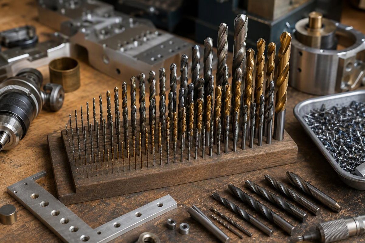
Use this drill bit diameter chart to translate fractional, number, letter and metric drill designations into nominal diameters. It covers fractional drills from 1/64 through 1 inch, number drills #80 through #1, letter drills A through Z and common metric sizes.
The listed diameter describes the drill, not a guaranteed finished hole. Choose the required hole first, select the corresponding drill and measure the result where fit matters.
Enter the required diameter to find exact or adjacent drill sizes.
Target Diameter
Searches every fractional, number and letter size in the chart plus the listed 0.5 mm metric steps.
Matching Nominal Sizes
Exact nominal matches for 0.250000 inch.
| Relation | Drill | Diameter | Difference |
|---|---|---|---|
| Exact | 1/4 (fractional); E (letter) | 0.250000 in 6.350 mm | 0.000000 in |
Source: fractional calculations use 1 inch = 25.4 mm; number and letter values follow the cited ICS Cutting Tools and Fastenal charts. Metric choices are limited to the 0.5 mm steps listed here.
How Drill Size Designations Compare
- Number drills run backward: #80 is the smallest in this chart; #1 is the largest.
- Letter drills run upward: A is smaller than B, and Z is the largest letter drill.
- Fractional values are exact: decimal inches are shown to six places and millimeters to three.
- Number and letter sizes are nominal decimal-inch diameters: their millimeter equivalents are rounded to three places.
- Metric drills do not need an equivalent inch drill: the decimal-inch value is provided for comparison.
The inch-to-metric calculations use the exact relationship 1 inch = 25.4 mm, as documented by NIST. Number and letter values are documented in the ICS Cutting Tools conversion chart and Fastenal’s decimal-equivalents chart. Fastenal’s 2024 jobber-drill product standard also lists #60 through #1, A through Z, fractional drills through 1/2 inch and selected metric sizes.
Fractional Drill Diameters From 1/64 To 1 Inch
| Size | Decimal in. | mm |
|---|---|---|
| 1/64 | 0.015625 | 0.397 |
| 1/32 | 0.031250 | 0.794 |
| 3/64 | 0.046875 | 1.191 |
| 1/16 | 0.062500 | 1.588 |
| 5/64 | 0.078125 | 1.984 |
| 3/32 | 0.093750 | 2.381 |
| 7/64 | 0.109375 | 2.778 |
| 1/8 | 0.125000 | 3.175 |
| 9/64 | 0.140625 | 3.572 |
| 5/32 | 0.156250 | 3.969 |
| 11/64 | 0.171875 | 4.366 |
| 3/16 | 0.187500 | 4.763 |
| 13/64 | 0.203125 | 5.159 |
| 7/32 | 0.218750 | 5.556 |
| 15/64 | 0.234375 | 5.953 |
| 1/4 | 0.250000 | 6.350 |
| 17/64 | 0.265625 | 6.747 |
| 9/32 | 0.281250 | 7.144 |
| 19/64 | 0.296875 | 7.541 |
| 5/16 | 0.312500 | 7.938 |
| 21/64 | 0.328125 | 8.334 |
| 11/32 | 0.343750 | 8.731 |
| 23/64 | 0.359375 | 9.128 |
| 3/8 | 0.375000 | 9.525 |
| 25/64 | 0.390625 | 9.922 |
| 13/32 | 0.406250 | 10.319 |
| 27/64 | 0.421875 | 10.716 |
| 7/16 | 0.437500 | 11.113 |
| 29/64 | 0.453125 | 11.509 |
| 15/32 | 0.468750 | 11.906 |
| 31/64 | 0.484375 | 12.303 |
| 1/2 | 0.500000 | 12.700 |
| 33/64 | 0.515625 | 13.097 |
| 17/32 | 0.531250 | 13.494 |
| 35/64 | 0.546875 | 13.891 |
| 9/16 | 0.562500 | 14.288 |
| 37/64 | 0.578125 | 14.684 |
| 19/32 | 0.593750 | 15.081 |
| 39/64 | 0.609375 | 15.478 |
| 5/8 | 0.625000 | 15.875 |
| 41/64 | 0.640625 | 16.272 |
| 21/32 | 0.656250 | 16.669 |
| 43/64 | 0.671875 | 17.066 |
| 11/16 | 0.687500 | 17.463 |
| 45/64 | 0.703125 | 17.859 |
| 23/32 | 0.718750 | 18.256 |
| 47/64 | 0.734375 | 18.653 |
| 3/4 | 0.750000 | 19.050 |
| 49/64 | 0.765625 | 19.447 |
| 25/32 | 0.781250 | 19.844 |
| 51/64 | 0.796875 | 20.241 |
| 13/16 | 0.812500 | 20.638 |
| 53/64 | 0.828125 | 21.034 |
| 27/32 | 0.843750 | 21.431 |
| 55/64 | 0.859375 | 21.828 |
| 7/8 | 0.875000 | 22.225 |
| 57/64 | 0.890625 | 22.622 |
| 29/32 | 0.906250 | 23.019 |
| 59/64 | 0.921875 | 23.416 |
| 15/16 | 0.937500 | 23.813 |
| 61/64 | 0.953125 | 24.209 |
| 31/32 | 0.968750 | 24.606 |
| 63/64 | 0.984375 | 25.003 |
| 1 | 1.000000 | 25.400 |
Number Drill Diameters From #80 To #1
| Size | Decimal in. | mm |
|---|---|---|
| #80 | 0.0135 | 0.343 |
| #79 | 0.0145 | 0.368 |
| #78 | 0.0160 | 0.406 |
| #77 | 0.0180 | 0.457 |
| #76 | 0.0200 | 0.508 |
| #75 | 0.0210 | 0.533 |
| #74 | 0.0225 | 0.572 |
| #73 | 0.0240 | 0.610 |
| #72 | 0.0250 | 0.635 |
| #71 | 0.0260 | 0.660 |
| #70 | 0.0280 | 0.711 |
| #69 | 0.0292 | 0.742 |
| #68 | 0.0310 | 0.787 |
| #67 | 0.0320 | 0.813 |
| #66 | 0.0330 | 0.838 |
| #65 | 0.0350 | 0.889 |
| #64 | 0.0360 | 0.914 |
| #63 | 0.0370 | 0.940 |
| #62 | 0.0380 | 0.965 |
| #61 | 0.0390 | 0.991 |
| #60 | 0.0400 | 1.016 |
| #59 | 0.0410 | 1.041 |
| #58 | 0.0420 | 1.067 |
| #57 | 0.0430 | 1.092 |
| #56 | 0.0465 | 1.181 |
| #55 | 0.0520 | 1.321 |
| #54 | 0.0550 | 1.397 |
| #53 | 0.0595 | 1.511 |
| #52 | 0.0635 | 1.613 |
| #51 | 0.0670 | 1.702 |
| #50 | 0.0700 | 1.778 |
| #49 | 0.0730 | 1.854 |
| #48 | 0.0760 | 1.930 |
| #47 | 0.0785 | 1.994 |
| #46 | 0.0810 | 2.057 |
| #45 | 0.0820 | 2.083 |
| #44 | 0.0860 | 2.184 |
| #43 | 0.0890 | 2.261 |
| #42 | 0.0935 | 2.375 |
| #41 | 0.0960 | 2.438 |
| #40 | 0.0980 | 2.489 |
| #39 | 0.0995 | 2.527 |
| #38 | 0.1015 | 2.578 |
| #37 | 0.1040 | 2.642 |
| #36 | 0.1065 | 2.705 |
| #35 | 0.1100 | 2.794 |
| #34 | 0.1110 | 2.819 |
| #33 | 0.1130 | 2.870 |
| #32 | 0.1160 | 2.946 |
| #31 | 0.1200 | 3.048 |
| #30 | 0.1285 | 3.264 |
| #29 | 0.1360 | 3.454 |
| #28 | 0.1405 | 3.569 |
| #27 | 0.1440 | 3.658 |
| #26 | 0.1470 | 3.734 |
| #25 | 0.1495 | 3.797 |
| #24 | 0.1520 | 3.861 |
| #23 | 0.1540 | 3.912 |
| #22 | 0.1570 | 3.988 |
| #21 | 0.1590 | 4.039 |
| #20 | 0.1610 | 4.089 |
| #19 | 0.1660 | 4.216 |
| #18 | 0.1695 | 4.305 |
| #17 | 0.1730 | 4.394 |
| #16 | 0.1770 | 4.496 |
| #15 | 0.1800 | 4.572 |
| #14 | 0.1820 | 4.623 |
| #13 | 0.1850 | 4.699 |
| #12 | 0.1890 | 4.801 |
| #11 | 0.1910 | 4.851 |
| #10 | 0.1935 | 4.915 |
| #9 | 0.1960 | 4.978 |
| #8 | 0.1990 | 5.055 |
| #7 | 0.2010 | 5.105 |
| #6 | 0.2040 | 5.182 |
| #5 | 0.2055 | 5.220 |
| #4 | 0.2090 | 5.309 |
| #3 | 0.2130 | 5.410 |
| #2 | 0.2210 | 5.613 |
| #1 | 0.2280 | 5.791 |
Letter Drill Diameters From A To Z
| Size | Decimal in. | mm |
|---|---|---|
| A | 0.2340 | 5.944 |
| B | 0.2380 | 6.045 |
| C | 0.2420 | 6.147 |
| D | 0.2460 | 6.248 |
| E | 0.2500 | 6.350 |
| F | 0.2570 | 6.528 |
| G | 0.2610 | 6.629 |
| H | 0.2660 | 6.756 |
| I | 0.2720 | 6.909 |
| J | 0.2770 | 7.036 |
| K | 0.2810 | 7.137 |
| L | 0.2900 | 7.366 |
| M | 0.2950 | 7.493 |
| N | 0.3020 | 7.671 |
| O | 0.3160 | 8.026 |
| P | 0.3230 | 8.204 |
| Q | 0.3320 | 8.433 |
| R | 0.3390 | 8.611 |
| S | 0.3480 | 8.839 |
| T | 0.3580 | 9.093 |
| U | 0.3680 | 9.347 |
| V | 0.3770 | 9.576 |
| W | 0.3860 | 9.804 |
| X | 0.3970 | 10.084 |
| Y | 0.4040 | 10.262 |
| Z | 0.4130 | 10.490 |
Common Metric Drill Diameters In 0.5 mm Steps
Metric drills are sold in more increments than this compact table can show. These 0.5 mm steps are reference points, not a claim that the nearest fractional, number or letter drill is interchangeable.
| Metric size | Decimal in. |
|---|---|
| 0.5 mm | 0.0197 |
| 1.0 mm | 0.0394 |
| 1.5 mm | 0.0591 |
| 2.0 mm | 0.0787 |
| 2.5 mm | 0.0984 |
| 3.0 mm | 0.1181 |
| 3.5 mm | 0.1378 |
| 4.0 mm | 0.1575 |
| 4.5 mm | 0.1772 |
| 5.0 mm | 0.1969 |
| 5.5 mm | 0.2165 |
| 6.0 mm | 0.2362 |
| 6.5 mm | 0.2559 |
| 7.0 mm | 0.2756 |
| 7.5 mm | 0.2953 |
| 8.0 mm | 0.3150 |
| 8.5 mm | 0.3346 |
| 9.0 mm | 0.3543 |
| 9.5 mm | 0.3740 |
| 10.0 mm | 0.3937 |
| 10.5 mm | 0.4134 |
| 11.0 mm | 0.4331 |
| 11.5 mm | 0.4528 |
| 12.0 mm | 0.4724 |
| 12.5 mm | 0.4921 |
| 13.0 mm | 0.5118 |
Choose The Hole Requirement Before The Nearest Drill
Do not automatically select the drill with the smallest numerical difference. Decide what the hole must do.
- Tapped hole: Use the tap maker’s drill recommendation for the complete thread marking and tap type. A standard cutting tap, forming tap, STI tap and pipe tap can require different holes. Compare the choices for a 1/4-inch tap and a 1/2-13 cutting tap.
- Bolt clearance hole: Use the specified close, normal or loose fit rather than matching the bolt’s nominal diameter. The difference is illustrated by the M6 clearance-hole sizes.
- Dowel, bearing or precision fit: Drilling alone may only be the roughing operation. Leave the required stock and finish by boring or reaming to the drawing requirement.
- Unknown replacement part: Record the feature and measurement location before choosing a nominal size. A measured worn hole is not automatically the original drawing diameter.
If substituting because the specified drill is unavailable, calculate the difference first. Letter F is 0.2570 inch while 1/4 inch is 0.2500 inch. The F drill is 0.0070 inch larger, not another name for a 1/4-inch drill.
Nominal Drill Diameter Does Not Guarantee Hole Diameter
A chart value is nominal. Fastenal’s 2024 jobber-drill standard cited above permits minus diameter tolerances that vary with drill range. Its requirements include 0 to −0.0007 inch for #30 through #1 drills and 0 to −0.0010 inch for F through Z drills. Those tolerances apply to that drill line, not universally to every drill.
The hole introduces another set of variables. OSG’s drilling technical guide identifies tool runout, cutting conditions, drill geometry, workpiece shape and clamping among the factors affecting hole accuracy. It specifically notes that runout and vibration can enlarge a drilled hole.
For a fit-sensitive job:
- Confirm the size designation and inspect the cutting edges.
- Measure the drill across its margins with a suitable micrometer if its identity is uncertain.
- Clamp the work rigidly and minimize chuck or holder runout.
- Drill a test hole in the same material and thickness when scrap is available.
- Deburr without rolling a large chamfer into the measuring surface.
- Measure the finished hole with an appropriate pin, plug gauge or bore-measuring tool.
That final measurement is the finished-part result. The chart remains the nominal tool reference.