
Screw Size Chart: US and Metric Machine Screws
Look up common US and metric machine screw diameters and threads, then measure length and verify the fit before ordering or drilling.
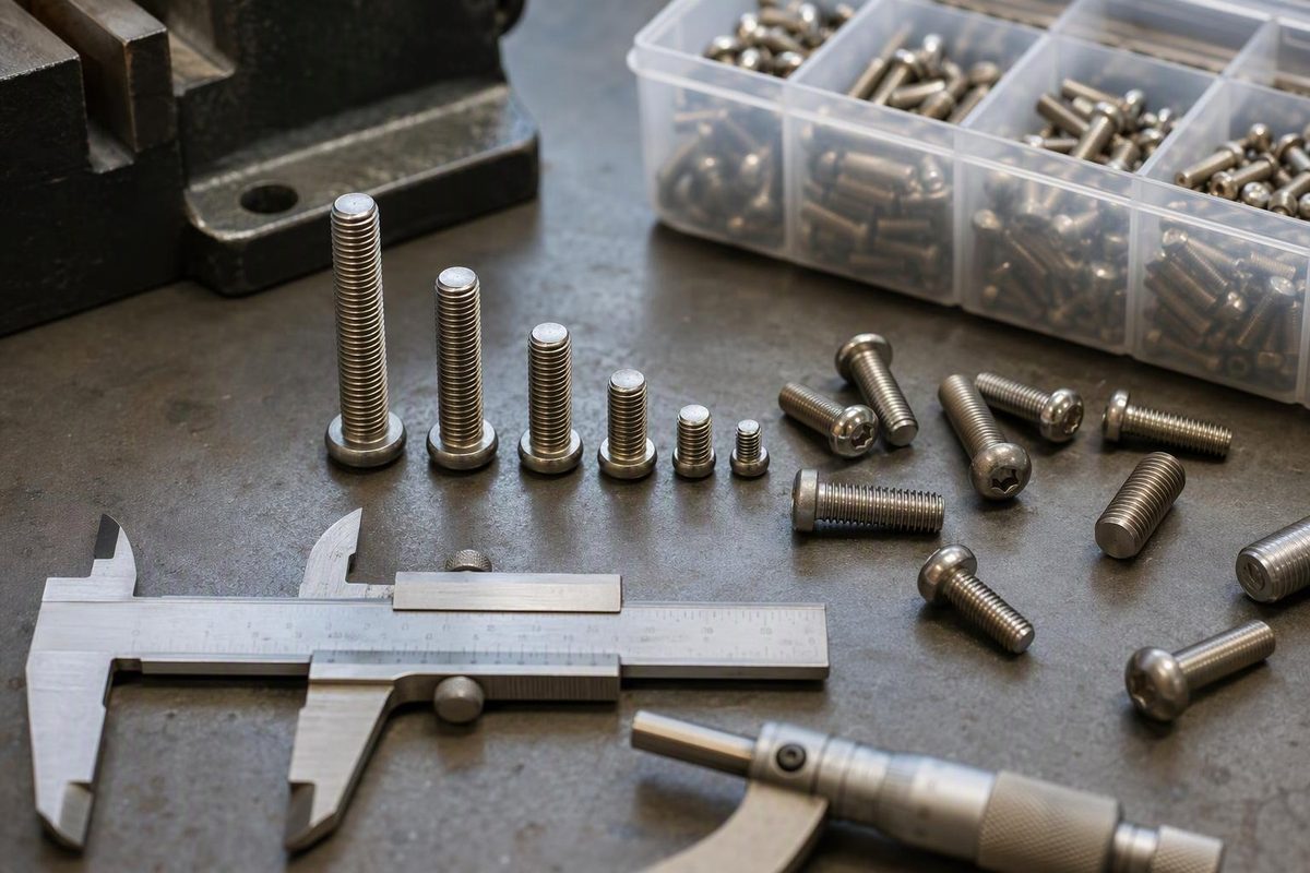
A screw size needs more than a diameter. Match the thread diameter, thread count or pitch, and length before choosing a replacement. Head style, drive, material and strength grade complete the specification.
These charts cover common machine-threaded screws and bolts used with nuts or tapped holes. They are identification references—not pilot-hole, tap-drill, clearance-hole or torque tables.
US screw size chart
Small US machine screws use numbered diameters such as #6 and #10; larger sizes commonly use inch fractions. UNC means Unified National Coarse; UNF means Unified National Fine. Both thread columns below give threads per inch (TPI).
Nominal diameters and thread counts follow Bolt Depot’s machine screw diameter table and US thread table. Millimeter values are calculated conversions, rounded to three decimal places.
| Screw size | Nominal diameter, in. | Diameter, mm | UNC, TPI | UNF, TPI |
|---|---|---|---|---|
| #0 | 0.0600 | 1.524 | — | 80 |
| #1 | 0.0730 | 1.854 | 64 | 72 |
| #2 | 0.0860 | 2.184 | 56 | 64 |
| #3 | 0.0990 | 2.515 | 48 | 56 |
| #4 | 0.1120 | 2.845 | 40 | 48 |
| #5 | 0.1250 | 3.175 | 40 | 44 |
| #6 | 0.1380 | 3.505 | 32 | 40 |
| #8 | 0.1640 | 4.166 | 32 | 36 |
| #10 | 0.1900 | 4.826 | 24 | 32 |
| #12 | 0.2160 | 5.486 | 24 | 28 |
| 1/4 | 0.2500 | 6.350 | 20 | 28 |
| 5/16 | 0.3125 | 7.938 | 18 | 24 |
| 3/8 | 0.3750 | 9.525 | 16 | 24 |
| 7/16 | 0.4375 | 11.113 | 14 | 20 |
| 1/2 | 0.5000 | 12.700 | 13 | 20 |
This is a common-size selection, not every Unified thread option.
Example: #10-32 × 1 in. means a #10 nominal diameter—0.190 inch—with 32 threads per inch and a specified length of 1 inch. A #10-24 screw has the same nominal diameter but a different thread spacing. The two do not fit the same nut or tapped hole.
The #10 is a diameter designation, not the screwdriver size. Head and tool dimensions must be checked separately; head size can vary for the same thread diameter.
Metric screw size chart
For ISO metric machine threads, M is followed by the nominal diameter in millimeters. Pitch is the axial distance from one thread crest to the next, also in millimeters—not threads per inch.
The following common coarse pitches are listed in Bolt Depot’s metric thread pitch table; M3.5 is also listed in Accu’s metric thread chart.
| Screw size | Nominal diameter, mm | Coarse pitch, mm |
|---|---|---|
| M2 | 2.0 | 0.40 |
| M2.5 | 2.5 | 0.45 |
| M3 | 3.0 | 0.50 |
| M3.5 | 3.5 | 0.60 |
| M4 | 4.0 | 0.70 |
| M5 | 5.0 | 0.80 |
| M6 | 6.0 | 1.00 |
| M8 | 8.0 | 1.25 |
| M10 | 10.0 | 1.50 |
| M12 | 12.0 | 1.75 |
Example: M6 × 1.0 × 25 means a 6 mm nominal thread diameter, 1.0 mm pitch and 25 mm specified length. A shortened label such as “M6 × 25” often leaves out the coarse pitch; verify it rather than assuming an unknown screw is coarse. Bolt Depot explains these conventions in its fastener notation guide.
A diameter conversion is not a replacement recommendation. A #10 screw converts to 4.826 mm; it is not an M5 screw. Match both diameter and thread spacing within the correct thread system.
Measure an unknown screw
Use a caliper, a thread-pitch gauge and a ruler or depth-measuring tool.
- Measure across the thread crests. Close the caliper’s outside jaws gently across the threaded portion, not across the head or down in the thread roots. Check more than one position and avoid damaged threads. This is the major-diameter measurement used to identify ordinary machine screws.
- Match the thread spacing. Try the appropriate inch or metric gauge leaves until the teeth seat along several threads without gaps. A caliper diameter alone cannot distinguish coarse from fine threads. Bolt Depot identifies a thread gauge as the normal measuring tool.
- Measure length from the correct surface. For pan, button, socket-cap and ordinary hex heads, measure from the underside of the head to the tip. For a countersunk flat head, measure overall, including the head. Special fasteners such as shoulder screws need their supplier drawing; see the length-measurement guidance.
- Verify the proposed match. After identifying the thread, try a known matching nut or an undamaged matching tapped hole by hand. Stop if it binds; do not use a driver to force a suspected match. A hand fit checks basic engagement, not load capacity.
The table values are nominal design dimensions, not exact acceptance readings for every finished screw. Thread tolerances apply, so use the diameter to identify a candidate, then confirm its thread and fit.
Before ordering or drilling
Record the full thread designation, length, head style, drive, material, coating and required strength grade. For a blind tapped hole, also check available depth so the screw can seat without bottoming.
Do not drill a hole straight from the nominal screw diameter:
- For a threaded hole, use the drill and tap guide chart for the identified thread and tap type.
- For wood or self-tapping screws, choose a pilot hole for the screw and material; do not use these machine-thread tables to choose their pilot holes.
- For a flat-head seat, match the countersink angle and depth to the screw.
Check the finished hole and seated screw before committing the rest of a hole pattern.