
Countersink and Drill Bit: Match the Hole to the Screw
Match drill diameter, countersink angle and depth to a flat-head screw, then cut and check the seat without weakening thin stock.
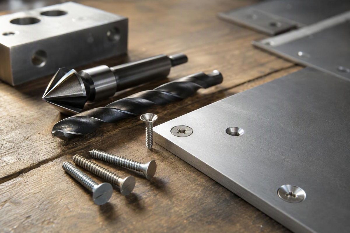
A drill bit makes the hole for the screw body; a countersink cuts the conical seat for its head. For a flat-head machine screw in a metal plate, choose these dimensions separately. The through-hole controls body clearance, while the countersink’s angle and finished diameter control head seating.
For a few holes in aluminum or steel, a separate drill and metal-cutting countersink let you check each operation before removing more material. A combination drill-countersink can save a tool change, but only if its drill diameter, angle and material rating suit the joint.
Choose the tools from the fastener and drawing
Before drilling, establish:
- Hole function: clearance through the upper plate, a wood-screw pilot, or a hole that will be tapped.
- Head geometry: included angle and specified head dimensions.
- Finished seat: countersink diameter and whether the head must be flush or recessed.
- Stock: material, thickness and room around the hole.
For a screw passing through a plate into a nut or tapped component, use the required clearance hole, not the tap-drill size. The M6 clearance-hole guide distinguishes close, ordinary and looser assembly fits. A light chamfer at a tapped-hole entrance is not the same operation as cutting a full screw-head seat.
Match the included angle—not just the screw diameter
The included angle is the full angle across the cone. Common inch-series flat-head screws use 82°, while common metric countersunk screws use 90°; examples are Bolt Depot’s 1/4-20 flat-head machine screw and M6 flat-head machine screw. Other angles exist, including 100° aerospace fasteners, so check the actual screw specification rather than treating inch or metric as a guarantee. The screw’s underside and the countersink must have matching angles for proper seating. Severance’s angle guide explains these distinctions.
Choose a cutter whose usable diameter range covers the specified countersink. It must reach the finished opening diameter, but its tip must also be small enough to enter the drilled hole. Its maximum diameter is its capacity—not automatically the diameter you should cut. Plunge depth determines the finished opening. SendCutSend’s countersinking guide describes these selection checks and recommends checking the fastener as the cut approaches depth.
Do not confuse a countersink with a counterbore: a countersink is conical; a counterbore is a cylindrical, flat-bottomed recess for a suitable flat-underhead fastener.
Check what a “combined drill and countersink” actually does
Woodworking combinations commonly have a drill passing through an adjustable countersink body. Snappy’s Gold Screw tools, for example, drill a pilot and cut an 82° seat in one operation, with an optional depth-stop collar. That does not establish suitability for a steel plate. Snappy’s product description identifies their wood-screw purpose.
Also watch for center drills sold as combined drills and countersinks. These typically make 60° center holes for machining between centers—not ordinary 82° or 90° screw seats. ICS Cutting Tools distinguishes these tools from adjustable wood-screw countersinks.
Check depth before cutting thin stock
For an ideal conical seat:
h = (D − d) ÷ [2 × tan(A ÷ 2)]
Here, h is axial countersink depth, D is the finished opening diameter, d is the through-hole diameter, and A is the included angle. Use the same units for all lengths; set your calculator to degrees when entering an angle in degrees. This geometry is given in Severance’s guide.
Suppose a drawing calls for a 12.0 mm opening, a 6.6 mm through-hole and a 90° seat. The calculated depth is 2.7 mm. Those are illustrative drawing dimensions, not a universal M6 recommendation. In 3 mm plate, that leaves only 0.3 mm of straight hole below the cone—a reason to reconsider the joint, not simply set the stop and drill.
The calculation predicts geometry; it does not verify strength or the finished part. If the seat consumes most of the stock thickness, consider thicker material or another fastening arrangement.
Drill, countersink, then verify
- Secure the work. Clamp it or use a secured drill vise. Wear eye protection, remove the chuck key and do not wear gloves while operating a drill press. Stop the spindle before adjustments or measurements. These are CCOHS drill-press precautions.
- Drill the specified hole. Check the finished hole size and that the screw passes through as intended before cutting its seat.
- Test on matching scrap. Use the same material and thickness. Follow the cutter maker’s speed guidance; do not assume the drilling RPM suits the countersink.
- Approach depth gradually. Make shallow cuts, stop the machine, clear chips with a brush rather than your fingers, and check the seat. Once a trial hole is correct, set the depth stop and verify the next hole. SendCutSend recommends this cut-and-check sequence.
- Inspect before tightening. Check the drawing dimensions, look for a smooth, concentric cone, and place the actual screw in the clean seat. Check head height with a straightedge or suitable measuring tool. A flush top alone does not prove that the angles match.
If the seat develops scallops or vibration, stop and check clamping, tool condition, speed and feed. ICS recommends single-flute countersinks when multi-flute tools chatter; changing cutter geometry may help more than continuing to deepen a rough hole.
Do not use tightening torque to pull a proud head into an incorrectly cut metal seat. Correct the geometry first; tightening belongs to the assembly step, not the machining step.