
Drill and Tap Guide Chart: Common Inch and Metric Sizes
Look up common UNC, UNF and metric cutting-tap drill sizes, then check thread marking, hole depth and finished fit before assembly.
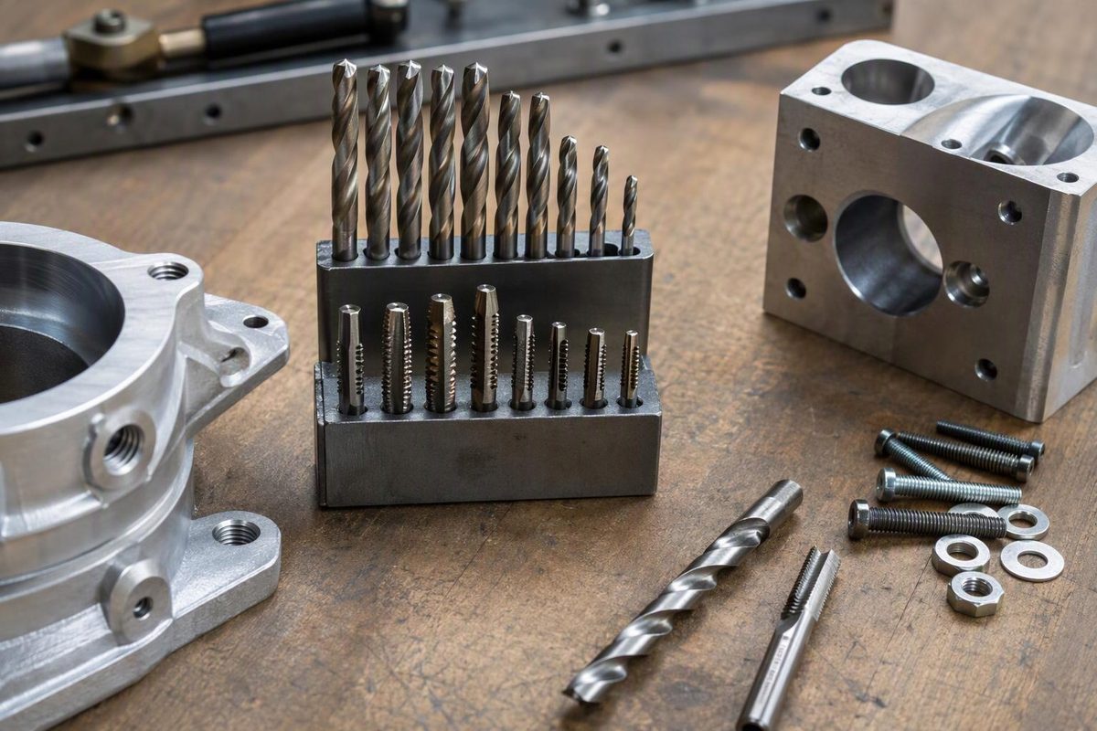
A common chart choice for a 1/4-20 cutting tap is a #7 drill (0.2010 inch); for M6 × 1.0, it is a 5.0 mm drill. The charts below cover common straight-thread cutting-tap jobs—not clearance holes, forming taps, pipe threads or thread-insert preparation.
Read the tap’s full marking before choosing the row. Diameter alone is not enough: 1/4-20 and 1/4-28 need different holes, as do M6 × 1.0 and M6 × 0.75.
Inch cutting-tap drill chart
These are conventional shop-chart choices, commonly associated with approximately 75% thread. They are starting drill selections, not finished-thread tolerances or guarantees of joint strength. The tap maker’s application guidance and drawing requirements take priority.
The selections and nominal decimal diameters below follow the 75% thread column in LittleMachineShop’s tap-drill chart, which is labeled for aluminum, brass and plastics. That source provides a separate 50% column for steel, stainless and iron; do not treat the table below as its recommendation for every material. The tap/drill pairings also agree with Carbide Depot’s UNC/UNF reference.
| Tap marking | Series | Tap drill | Nominal drill diameter, in. |
|---|---|---|---|
| #4-40 | UNC | #43 | 0.0890 |
| #6-32 | UNC | #36 | 0.1065 |
| #8-32 | UNC | #29 | 0.1360 |
| #10-24 | UNC | #25 | 0.1495 |
| #10-32 | UNF | #21 | 0.1590 |
| 1/4-20 | UNC | #7 | 0.2010 |
| 1/4-28 | UNF | #3 | 0.2130 |
| 5/16-18 | UNC | F | 0.2570 |
| 5/16-24 | UNF | I | 0.2720 |
| 3/8-16 | UNC | 5/16 in. | 0.3125 |
| 3/8-24 | UNF | Q | 0.3320 |
| 7/16-14 | UNC | U | 0.3680 |
| 7/16-20 | UNF | 25/64 in. | 0.3906 |
| 1/2-13 | UNC | 27/64 in. | 0.4219 |
| 1/2-20 | UNF | 29/64 in. | 0.4531 |
| 5/8-11 | UNC | 17/32 in. | 0.5312 |
| 5/8-18 | UNF | 37/64 in. | 0.5781 |
| 3/4-10 | UNC | 21/32 in. | 0.6562 |
| 3/4-16 | UNF | 11/16 in. | 0.6875 |
In 1/2-13, the first number is nominal thread diameter in inches; 13 means threads per inch. A #7 drill is a numbered drill, not a 7 mm bit. Letters such as F and Q are drill-size designations too. Use the drill bit diameter chart when comparing what is actually in your drill index.
Metric cutting-tap drill chart
Metric markings give nominal diameter and pitch in millimetres. M8 × 1.25 means an 8 mm nominal thread with 1.25 mm between successive threads—not 1.25 threads per millimetre.
These conventional selections follow Carbide Depot’s metric tap chart. Use the metric drill diameter shown; a nearby inch bit is not automatically an equivalent substitute.
| Tap marking | Tap drill, mm |
|---|---|
| M2 × 0.40 | 1.60 |
| M2.5 × 0.45 | 2.05 |
| M3 × 0.50 | 2.50 |
| M3.5 × 0.60 | 2.90 |
| M4 × 0.70 | 3.30 |
| M5 × 0.80 | 4.20 |
| M6 × 1.00 | 5.00 |
| M8 × 1.25 | 6.80 |
| M8 × 1.00 | 7.00 |
| M10 × 1.50 | 8.50 |
| M10 × 1.25 | 8.80 |
| M12 × 1.75 | 10.20 |
| M12 × 1.25 | 10.80 |
| M14 × 2.00 | 12.00 |
| M16 × 2.00 | 14.00 |
Published charts can differ slightly: for example, LittleMachineShop lists 10.3 mm for M12 × 1.75, rather than 10.2 mm. Resolve that choice against your tap maker’s recommendation and required thread limits before drilling a finished part.
When these sizes are not the right choice
A clearance hole is a different feature. The bolt passes through it rather than threading into it. For a two-plate joint, identify which plate gets the tapped hole and which gets clearance; see the M6 clearance-hole guide.
More thread percentage is not automatically better. Guhring explains that thread strength is not directly proportional to thread percentage and recommends 60–70% for most applications to improve tap life. Its advice is not permission to enlarge every hole: the material, required thread limits and joint requirements still govern. Follow the tap maker’s selection guidance, especially for steel and stainless.
Forming taps need their own hole dimensions. For example, Guhring’s forming-tap table gives 5.56 mm for M6 × 1.0 at 65% thread, distinctly larger than the 5.0 mm cutting-tap selection above. Do not transfer cutting-tap sizes to a forming operation. Use the forming-tap chart for the selected tool and percentage.
NPT and insert taps are outside these tables. If the marking includes NPT or STI, stop and obtain the matching tap or insert-system instructions.
Drill, tap and check the actual part
- Record the requirement. Note the complete thread marking, material, hole position and required full-thread depth. Keep drilled depth separate from usable thread depth.
- Secure and drill. Clamp the work or use a drill vise; do not hold stock by hand. Wear eye protection, remove the chuck key and stop the machine before measuring. Do not wear gloves around the rotating drill press. These are core CCOHS drill-press precautions.
- Inspect before tapping. Remove burrs and chips, check hole position, and verify the bore with suitable measuring tools or pin gauges where size matters. The number stamped on the drill is a nominal tool size, not an inspection result.
- Start square and control depth. Use a tap guide aligned with the drilled hole and the lubrication specified for the tool and material. In a blind hole, leave room for the tap’s chamfer lead and chip clearance. Guhring warns that running a tap into the hole bottom can cause breakage; a shorter chamfer lead may help where deeper drilling is not permitted. See its threading troubleshooting guidance.
- Check before tightening. Clean the thread and try the correct fastener by hand without forcing it. Confirm that it reaches the required engagement without bottoming. Treat that as an assembly check, not proof of thread tolerance; use the specified thread plug gauges when the drawing requires verification.
For tap styles and cutting technique, use the tap and die selection guide.