
1-1/4 NPT Dimensions, but Diameter Varies
The listed 1.660-inch pipe-body OD is not the male-thread diameter at every axial position, because the threaded-section diameter changes along the taper.
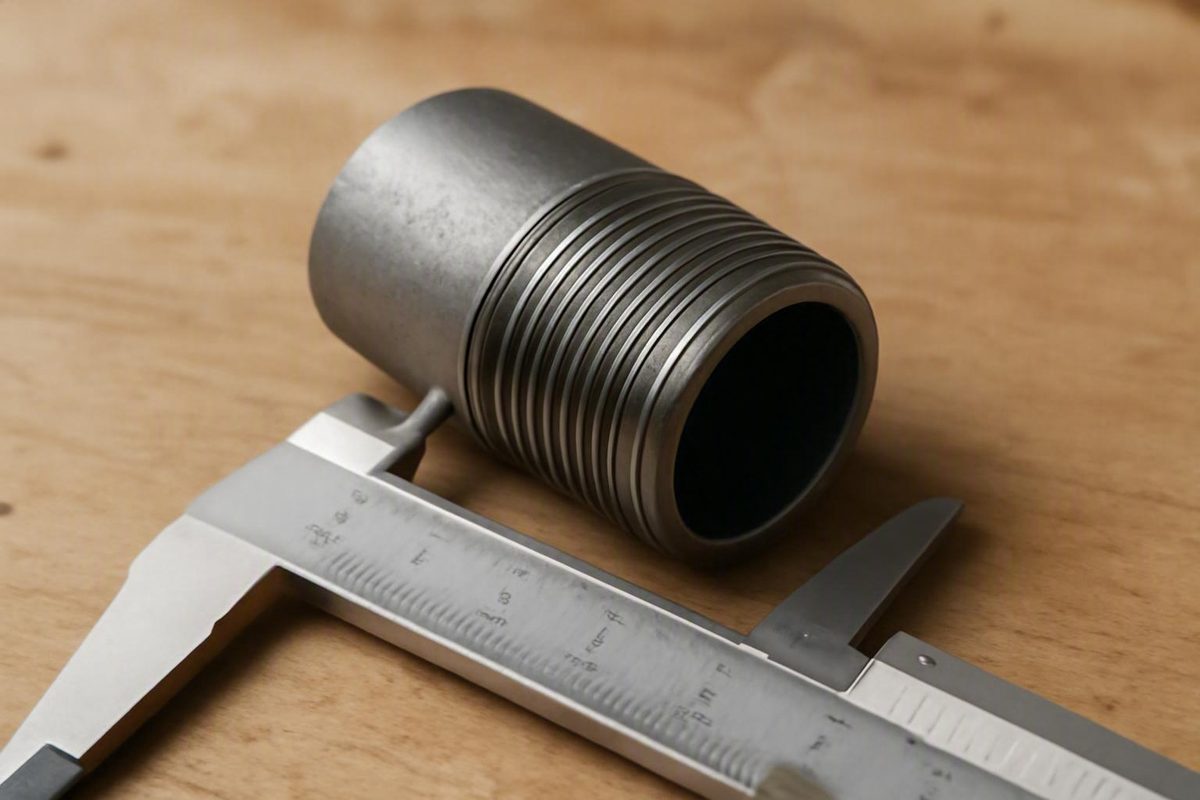
The full designation is 1-1/4-11.5 NPT: a nominal 1-1/4-inch pipe size with 11.5 threads per inch. Its principal basic dimensions include a 1.660-inch pipe outside diameter, 0.08696-inch pitch, 60-degree thread form, and 1-in-16 taper on diameter. These values are reported consistently across secondary NPT dimensional references, but they are not a substitute for the current governing standard or toolmaker data.
Those numbers describe different features of the connection. The nominal size is not a measured diameter. The listed 1.660-inch pipe-body OD is not the male-thread diameter at every axial position, because the threaded-section diameter changes along the taper. Engagement dimensions such as L1 and L2 also have different endpoints and meanings.
This guide separates those values for identification, preliminary machining, and shop planning.
1-1/4 NPT dimensions at a glance
The following are basic dimensions from secondary technical references, not complete manufacturing tolerances, gauge limits, or acceptance criteria. Extra decimal places distinguish calculated reference planes; they do not imply that a caliper or ordinary machining process must reproduce that precision. The detailed E and L values are supported by the Machining Doctor 1-1/4-11.5 NPT table, while the taper expressions are also reported by established NPT chart references.
| Property | Inches / imperial | Millimeters / metric |
|---|---|---|
| Full designation | 1-1/4-11.5 NPT | — |
| Nominal pipe size | 1-1/4 in | Nominal only |
| Pipe outside diameter, D | 1.660 in | 42.164 mm |
| Thread density | 11.5 TPI | — |
| Pitch, P | 0.08696 in | 2.209 mm |
| Included thread angle | 60° | 60° |
| Flank angle | 30° per side | 30° per side |
| Taper on diameter | 1 in 16 | 1 mm in 16 mm |
| Taper per foot | 3/4 in/ft | 62.5 mm/m |
| Taper angle from center axis | About 1.79° | About 1°47′24″ |
| Basic thread height, h | 0.06957 in | 1.767 mm |
| Pitch diameter at pipe end, E0 | 1.55713 in | 39.551 mm |
| Basic hand-tight length, L1 | 0.420 in | 10.668 mm |
| Pitch diameter at L1 plane, E1 | 1.58338 in | 40.218 mm |
| Maximum useful external-thread length, L2 | 0.7068 in | 17.953 mm |
| Pitch diameter at L2 plane, E2 | 1.60130 in | 40.673 mm |
The short shop specification is:
1-1/4-11.5 NPT — 1.660-inch pipe OD, 11.5 TPI, 0.08696-inch pitch, 60-degree form, and 3/4-inch-per-foot taper on diameter.
Three distinctions prevent most lookup errors:
- 1-1/4 inches is the nominal trade size, not an expected caliper diameter.
- 1.660 inches is the standard pipe-body OD, not a constant diameter across the tapered male thread.
- L1 and L2 are different axial dimensions: L1 locates the basic theoretical hand-tight plane, while L2 identifies the maximum useful external-thread length.
For production, gauging, or acceptance, use the current governing standard, the drawing, and the applicable tooling documentation rather than treating this summary as a complete thread specification.
Why a 1-1/4-inch NPT connection measures larger than 1.25 inches
The “1-1/4” in 1-1/4 NPT is a nominal pipe size, sometimes called a trade size. It is not a direct statement of the pipe OD, thread major diameter, pitch diameter, female opening, or preliminary tap hole.
Nominal 1-1/4-inch pipe has a listed outside diameter of 1.660 inches, or 42.164 mm. That naming convention explains why a correct fitting looks substantially larger than 1.250 inches. Treating 1.25 inches as the expected male-thread diameter will point toward the wrong size.
The pipe body and tapered thread must also be distinguished. The 1.660-inch figure describes the standard pipe outside diameter. On the external thread, diameter varies with axial position: it becomes smaller toward the free pipe end and larger toward the unthreaded pipe body.
A threaded-section caliper reading below 1.660 inches can therefore be consistent with 1-1/4 NPT. Its meaning depends on:
- whether the measurement was taken on the pipe body or the thread;
- the axial position along the taper;
- whether the jaws crossed intact, complete thread crests;
- whether coating, corrosion, wear, damage, or crest flattening affected contact.
Pipe schedule changes the bore and wall thickness rather than the listed pipe OD or nominal external NPT connection. For example, nominal 1-1/4-inch Schedule 40 and Schedule 80 pipe are both listed at 1.660-inch OD. Schedule 40 is listed with a 1.380-inch ID and 0.140-inch wall, while Schedule 80 is listed with a 1.278-inch ID and 0.191-inch wall in Oster’s pipe-size and thread-dimension reference.
| Nominal pipe | Schedule | Outside diameter | Inside diameter | Wall thickness |
|---|---|---|---|---|
| 1-1/4 in | 40 | 1.660 in | 1.380 in | 0.140 in |
| 1-1/4 in | 80 | 1.660 in | 1.278 in | 0.191 in |
Thus, two pipes can have the same nominal external connection while having materially different bores and wall sections. Those questions require component-, material-, and service-specific design information.
Thread pitch, taper, and profile geometry
For 1-1/4-11.5 NPT, pitch follows from the thread count:
P = 1 ÷ 11.5 = 0.0869565 in per thread
Converting to millimeters:
0.0869565 × 25.4 ≈ 2.209 mm
Accordingly, 2.209 mm is a useful converted pitch, while 2.21 mm is an appropriately rounded shop value. Neither value makes this a metric thread; NPT remains an inch-defined pipe-thread form.
The thread has a 60-degree included angle, or 30 degrees per flank. The listed basic thread height is 0.06957 inch, or 1.767 mm. These are profile-reference values, not stand-alone inspection limits.
Understanding the two different angles
The profile angle and taper angle describe different geometry:
- 60 degrees is the included angle between the thread flanks.
- About 1.79 degrees is the angle between the tapered thread envelope and the pipe center axis.
Do not set a compound, taper attachment, or inspection setup to 60 degrees when the task is to generate the NPT taper. Conversely, the taper angle does not define the cutting-tool profile.
NPT changes by one unit of diameter for every 16 units of axial length. This 1-in-16 taper on diameter is equivalent to 3/4 inch of diameter change per foot. The corresponding angle from the center axis is approximately 1 degree 47 minutes 24 seconds, or 1.7899 degrees, according to the Engineers Edge NPT taper chart.
Because the taper is stated on diameter, the ideal diameter change over axial distance L is:
\Delta D = L ÷ 16
For example, moving 0.420 inch along the ideal taper changes the basic diameter by:
0.420 ÷ 16 = 0.02625 in
That matches the difference between the listed E0 and E1 pitch diameters:
1.58338-1.55713 = 0.02625 in
This relationship explains why diameter readings vary along a male thread. It does not replace proper gauging: measurement position, crest condition, truncation, and thread-form error all affect what a caliper contacts.
How to read E0, E1, E2, L1, L2, L3, and L4
The lettered values in an NPT table locate diameters and lengths on an idealized tapered thread. They are easiest to understand as reference planes rather than unrelated numbers.
     PIPE END                                      PIPE BODY
  smaller diameter                           larger diameter
        │                                             │
        ▼                      taper increases ──────►
┃ /\/\/\/\/\/\/\/\/\/\/\/\/\/\/\/\/\/\/\/\/\/┃
        A---------B----------------C-------------------D
        │         │                │                   │
        E0        E1               E2                  end of L4
        │<-- L1 ->│
        │<----------- L2 --------->│
                  │<-- L3 -->│
        │<---------------- L4 ----------------------->│

        A = pipe-end reference plane
        B = basic hand-tight plane
        C = maximum useful external-thread plane
        D = end of overall external-thread length

        External-thread diameter increases toward the pipe body.
The diagram is schematic and not to scale. L3 is a listed wrenching allowance associated with make-up beyond the hand-tight condition; it is not a promise that every assembled joint will advance by exactly that distance.
E0: pitch diameter at the pipe end
E0 is 1.55713 inches, or 39.551 mm.
It is the basic external pitch diameter at the pipe-end reference plane. It is neither the pipe-body OD nor a direct crest-to-crest caliper diameter.
L1 and E1: the basic hand-tight plane
L1 is 0.420 inch, or 10.668 mm, corresponding to approximately:
0.420 × 11.5 = 4.83 threads
L1 is the basic theoretical hand-tight engagement length for nominal, correctly formed mating threads. At that axial plane, E1 is 1.58338 inches, or 40.218 mm.
“Theoretical” is important. Boshart’s explanation of theoretical NPT engagement likewise cautions that actual engagement can differ from ideal chart values.
L2 and E2: maximum useful external thread
L2 is 0.7068 inch, or 17.953 mm, corresponding to approximately:
0.7068 × 11.5 = 8.13 threads
L2 is the maximum useful external-thread length, not the basic hand-tight length. At the L2 plane, E2 is 1.60130 inches, or 40.673 mm.
E2 is larger than E1, and E1 is larger than E0, because the three planes are progressively farther from the small end of the external taper.
L3: wrenching allowance
L3 is listed as 0.2609 inch, or 6.627 mm.
L3 identifies a wrenching allowance. It is not a universal achieved assembly length, a torque specification, or a guaranteed number of additional turns.
L4: overall external-thread length
L4 is listed as 1.0085 inches, or 25.616 mm.
This is the overall external-thread length, including the runout or vanish-thread region. It should not be confused with useful-thread length L2 or actual assembled engagement.
L5: last complete-profile thread
Where a drawing uses L5, it identifies the length to the last complete-profile external thread. For this size, L5 is listed as 0.5329 inch, or 13.536 mm.
The L3, L4, and L5 values above come from the same detailed 1-1/4-11.5 NPT dimensional reference. They remain secondary-reference basic dimensions, not complete acceptance limits.
Conflicting commercial labels
A MISUMI commercial chart publishes 0.2074 inch as “hand-tight engagement” and 0.4252 inch as “effective thread length” for this nominal size. Those labels and values do not reconcile with the L1 = 0.420-inch and L2 = 0.7068-inch convention used by the detailed dimensional sources. The available evidence does not establish that the chart uses the same endpoints or reference planes; its alternative commercial thread-length labels should therefore not be substituted for L1 or L2.
The safe practice is to preserve the symbols shown on the applicable drawing or standard. Never transfer a bare “engagement” or “thread length” value into a machining setup until its endpoints and definition are known.
Tap-drill and hole-preparation options
There is no single preliminary-hole value that can be separated from the method used to produce the internal thread. A hole intended for taper reaming is prepared differently from one that will be tapped directly.
| Hole-preparation method | Secondary-reference starting value | Metric equivalent | Qualification |
|---|---|---|---|
| Preliminary drilling before taper reaming | 1.4688 in | 37.3063 mm | Follow with a 3/4-in-per-foot taper reamer |
| Direct tapping without taper reaming | 1.4844 in | 37.7031 mm | Starting reference, not universal |
| Alternative tool-table recommendation | — | About 37.00 mm | Shows variation among published recommendations |
| Straight NPS preparation | 1.500 in | 38.1 mm | NPS reference, not the standard NPT choice |
The first two values and the 1.500-inch NPS comparison appear together in TorqBolt’s NPT tapping-drill table. That reference calls for a 1.4688-inch preliminary hole when a taper reamer will follow, with reaming at 3/4 inch per foot. For direct tapping without reaming, it lists 1.4844 inches.
A BAER tool-oriented table lists approximately 37.00 mm as the tapping drill. The vendor’s NPT technical table should be treated as tool guidance, not proof of one universal hole size.
Choosing between reaming and direct tapping
Direct tapping omits the separate reaming operation. The appropriate process and starting hole can depend on:
- workpiece material and hardness;
- through-hole or blind-hole geometry;
- tap style and manufacturer;
- machine power and rigidity;
- desired thread percentage;
- whether a taper reamer is used;
- cutting fluid and chip evacuation;
- required tool life and inspection method.
The 1.500-inch value is associated with straight NPS preparation in the cited table. It should not be transferred to a tapered NPT operation merely because it is a convenient fractional size.
For production work, follow the tap manufacturer’s drill and reamer recommendations, then inspect according to the drawing and current governing procedure. These starting values do not establish internal-thread limits, boss dimensions, wall thickness, pressure capacity, or acceptance criteria.
How to identify a 1-1/4 NPT thread in the shop
Use several observations together. One diameter measurement is not enough to identify or accept a tapered pipe thread.
1. Inspect markings and context
Look for cast, stamped, engraved, or molded markings such as:
- 1-1/4 NPT;
- 1-1/4 FNPT or MNPT;
- FIP or MIP;
- a manufacturer and part number;
- BSP, G, R, Rc, NPS, or NPTF markings indicating another form.
Component origin or application can suggest a thread family, but it is not proof.
2. Take a preliminary diameter measurement
Use calipers to measure a male thread across intact crests. On a female fitting, the opening can be measured only as an approximate identification aid. Avoid incomplete or damaged threads.
Record the axial position of every male-thread measurement. A thread-identification reference recommends checking around the fourth or fifth full thread before comparing the result with a table because a tapered-thread diameter changes along its length; its NPT and BSP identification tables also illustrate why nominal size is not measured diameter.
A reading around 1.58 inches does not necessarily contradict the 1.660-inch pipe OD. The numbers can describe different features:
- 1.660 inches: listed pipe-body OD;
- a smaller male reading: diameter at a selected point on the external taper;
- about 1.58 inches: an approximate female-opening screening value in an identification chart;
- 1.58338 inches: basic E1 pitch diameter, not a crest-to-crest major diameter.
The approximate 1.58-inch female opening is an identification value rather than a complete internal-thread specification, as shown in Trimantec’s thread-identification guide.
3. Confirm 11.5 TPI
Use an imperial thread-pitch gauge and select the 11.5-TPI leaf. It should seat over several undamaged threads without visible rocking or progressively losing alignment.
A ruler can provide a rough count, but a pitch gauge is preferable. Pitch is especially important when distinguishing 1-1/4 NPT from 1-1/4 BSP, which is listed at 11 TPI.
4. Verify the taper
Measure the male thread at two known axial positions. Diameter should increase as the measurement moves toward the pipe body.
For an ideal 1-in-16 taper on diameter, a 0.500-inch axial separation corresponds to:
0.500 ÷ 16 = 0.03125 in diameter change
A caliper check can reveal an obvious taper, but it cannot verify the complete thread form or acceptance limits.
5. Inspect condition
Before relying on measurements, check for:
- flattened or rolled-over crests;
- corrosion, scale, paint, plating, or sealant residue;
- cross-threading or galling;
- impact damage;
- incomplete runout threads;
- distorted plastic threads;
- out-of-round components.
Clean the part only by a method appropriate to its material and intended service.
6. Use the required gauge when acceptance matters
Pitch, diameter, and taper checks can support preliminary identification. Manufacturing or acceptance inspection should use the gauge and procedure required by the drawing or current governing standard.
This article does not establish gauge class, permissible standoff, tolerance limits, or a formal inspection sequence.
Engagement, sealant, and assembly limits
“Engagement” can refer to several different dimensions:
- L1: basic theoretical hand-tight length, 0.420 inch;
- L2: maximum useful external-thread length, 0.7068 inch;
- L3: listed wrenching allowance, 0.2609 inch;
- actual assembled engagement: the position reached by the particular male and female parts.
L1 assumes nominal, correctly formed mating threads. It does not guarantee that every fitting will become hand-tight at exactly 0.420 inch. Thread variation, wear, deformation, coating, contamination, sealant, material compliance, and prior use can change the observed position.
A Dixon industrial catalog separately lists 11/16 inch as “normal NPT engagement” for 1-1/4-inch thread and warns that the figure does not allow for tapping or threading variation. Because its endpoints are not reconciled with L1, L2, or L3, the catalog engagement value should not be relabeled as any of those dimensions or as guaranteed wrench-tight engagement.
Does ordinary NPT require sealant?
Where a leak-tight ordinary NPT joint is required, the cited manufacturer guidance describes assembly with a compatible thread sealant such as suitable PTFE tape or jointing compound. NPTF is different: it is a related dry-seal form and should not be treated as identical to ordinary NPT in sealing behavior, manufacturing detail, or gauging. CPC’s pipe-thread overview distinguishes the 60-degree NPT form from other pipe-thread systems and describes the use of sealant on NPT joints.
Select and apply sealant according to the fitting, equipment, and sealant manufacturers’ instructions. The appropriate product and make-up procedure depend on the actual components and service conditions; this dimensional guide does not establish service compatibility.
Avoid universal torque and turn counts
There is no universal torque or fixed wrench-turn count for every 1-1/4 NPT joint. Joint material, wall thickness, fitting geometry, sealant, thread variation, coating, and condition affect make-up.
Do not assume that additional tightening will correct an incorrect thread, damaged component, or mismatched fitting. If the connection binds unexpectedly, remains conspicuously loose, or begins cross-threaded, stop and confirm the designation and condition. Follow the component manufacturer’s assembly procedure rather than deriving a torque from the dimensional table.
Do not confuse NPT with NPS, NPTF, or BSP
Similar nominal labels do not establish interchangeability. Identify the thread family as well as its nominal size before cutting, ordering, or assembling a fitting.
| Thread family | Taper or straight | Included angle | 1-1/4 pitch reference | Main distinction |
|---|---|---|---|---|
| NPT | Tapered | 60° | 11.5 TPI | Ordinary tapered American pipe thread |
| NPS | Straight | Corresponding American pipe form | Depends on designation | Parallel rather than tapered |
| NPTF | Tapered | 60° | Related NPT-series pitch | Dry-seal form; not identical to ordinary NPT |
| BSP | Parallel or tapered, depending on designation | 55° | 11 TPI | Whitworth-type profile and different pitch |
NPT versus NPS
NPT is tapered; NPS is straight.
The 1.500-inch drill shown beside the cited NPT drill data is a straight-NPS reference. It is not the standard substitute for the smaller preliminary holes identified for the tapered-NPT processes. Confirm whether the print calls for NPT or NPS before selecting the tap, reamer, and drill.
NPT versus NPTF
NPTF is related to NPT but intended as a dry-seal form. A chart may group NPT and NPTF for identification because their broad size and pitch characteristics are related, but that does not make them identical in truncation, sealing action, manufacturing, or gauging.
Use the exact designation on the drawing and component. A part beginning to thread into a port does not demonstrate compliance with an NPTF requirement.
NPT versus BSP
At nominal 1-1/4-inch size:
- NPT uses 11.5 TPI and a 60-degree form.
- BSP uses 11 TPI and a 55-degree form.
Their nominal labels and approximate diameters can look similar, but their pitches and profiles differ. The Valves Online comparison lists the corresponding 1-1/4 BSP thread at 11 TPI and describes the 55-degree BSP form versus the 60-degree NPT form.
That does not make the connection interchangeable.
Standards hierarchy and shop checklist
The dimensional sources used here are secondary references. One cited chart expressly identifies an older ANSI/ASME B1.20.1 edition, so it should not be assumed to reproduce every current manufacturing, gauging, or inspection requirement.
Use this hierarchy:
- This article: dimensional lookup, identification, and preliminary planning.
- Tap and tool manufacturer data: drill, reamer, tap, lubrication, and setup.
- Component and sealant manufacturer instructions: joint make-up and application compatibility.
- Current ASME B1.20.1 requirements: manufacturing dimensions, tolerances, gauging, inspection, and acceptance.
Before starting work, confirm:
- [ ] The designation is 1-1/4-11.5 NPT.
- [ ] The listed pipe OD is 1.660 inches, not 1.250 inches.
- [ ] The pitch is 11.5 TPI.
- [ ] The taper is 1 in 16 on diameter.
- [ ] The thread profile is 60 degrees.
- [ ] E0, E1, and E2 are pitch diameters at different axial planes.
- [ ] L1, L2, L3, L4, and actual engagement are kept distinct.
- [ ] The preliminary hole reflects whether taper reaming will be used.
- [ ] The adjacent 1.500-inch NPS drill is not substituted for NPT.
- [ ] NPTF and BSP data are not substituted for ordinary NPT.
- [ ] The drawing, required gauge, and current standard control acceptance.
- [ ] Manufacturer instructions control final assembly and sealant selection.
Frequently asked questions
What is the actual outside diameter of 1-1/4 NPT pipe?
Nominal 1-1/4-inch pipe has a listed outside diameter of 1.660 inches, or 42.164 mm. That is the standard pipe-body OD, not a constant male-thread diameter at every axial position. The threaded area tapers and can produce smaller caliper readings near the free end, as summarized in this NPT pipe and port size chart.
How many threads per inch does 1-1/4 NPT have?
The full designation is 1-1/4-11.5 NPT, so the thread has 11.5 threads per inch. Its corresponding pitch is approximately 0.08696 inch, or 2.209 mm, per thread.
What tap-drill size is used for 1-1/4 NPT?
It depends on the process. A detailed secondary reference lists 1.4688 inches (37.3063 mm) as the preliminary hole before taper reaming and 1.4844 inches (37.7031 mm) for direct tapping without a reamer.
Use those as method-specific starting references, not universal requirements. Follow the tap manufacturer’s recommendation for the material, tool design, machine, and intended thread condition. The nearby 1.500-inch figure is associated with straight NPS preparation rather than the standard tapered-NPT process.
Why might a 1-1/4 NPT male thread measure less than 1.660 inches?
The 1.660-inch value is the listed pipe-body OD. An external NPT thread decreases in diameter toward its free end, so a caliper placed on the threaded section can read less than 1.660 inches.
The reading also depends on axial position, crest condition, coating, wear, damage, and whether the jaws contact complete threads. Record the measurement location, then confirm 11.5 TPI and taper rather than identifying the connection from one diameter alone.
Can 1-1/4 NPT be connected to 1-1/4 BSP?
No—not as a standards-compliant interchangeable connection. Nominal 1-1/4 NPT uses 11.5 TPI and a 60-degree form, while the corresponding BSP reference uses 11 TPI and a 55-degree Whitworth form. Manufacturer guidance on NPT and BSP thread forms likewise identifies the different profiles.
The parts may appear close in diameter and may begin to engage, but the pitches and forms do not match. Do not force them together or rely on sealant to correct the mismatch. Use a properly specified adapter when conversion between NPT and BSP is required.