
A 1/4-Inch Tap's Full Marking Sets the Drill Bit Size
Use #7 for a standard 1/4-20 cutting tap or #3 for a standard 1/4-28 cutting tap. NPT, STI and forming taps require different hole dimensions.
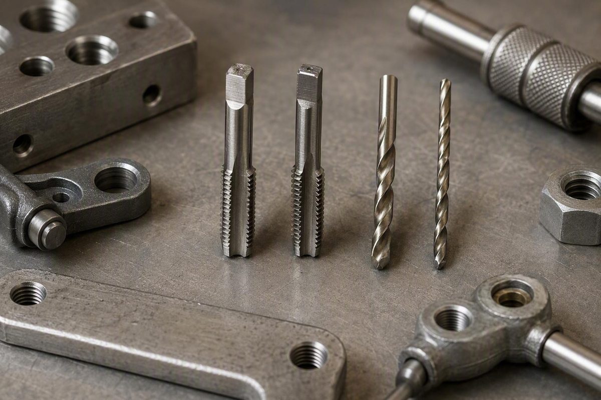
Quick answer: the drill size depends on the tap’s full marking
For a standard 1/4-20 UNC cutting tap, use a #7 drill. For a standard 1/4-28 UNF cutting tap, use a #3 drill. The two sizes are not interchangeable because the thread pitches require different pilot-hole diameters.
| Tap marking | Primary drill | Decimal diameter | Metric equivalent | Fractional alternative | Qualification |
|---|---|---|---|---|---|
| 1/4-20 UNC cutting tap | #7 | 0.2010 in | Approximately 5.11 mm; 5.1 mm is a close substitute | 13/64 in, approximately 0.2031 in | 13/64 in is slightly larger than #7, not identical |
| 1/4-28 UNF cutting tap | #3 | 0.2130 in | Approximately 5.41 mm | 7/32 in, approximately 0.2188 in | 7/32 in is larger than #3 and is not the preferred size when #3 is available |
The numbered-drill and metric dimensions are listed in the Slugger Tool tap-drill reference, while the fractional alternatives and their decimal dimensions appear in the Lincoln Machine chart.
The nominal 1/4-inch diameter alone is not enough information. You must also identify the pitch, thread standard, and tap type. A tap marked 1/4-20 cuts 20 threads per inch, while a 1/4-28 tap cuts 28 threads per inch. Although both have a nominal 1/4-inch major diameter, they do not use the same pilot hole.
Do not select a bit merely because a drill index or chart labels it “for a 1/4-inch tap.” Read the complete marking on the tap first. If the marking is incomplete or illegible, check the original package, the labeled slot in the tap set, or the manufacturer’s catalog information.
Important: These recommendations apply to ordinary straight-thread cutting taps. Do not apply them blindly to NPT pipe taps, forming or roll taps, STI taps, threaded-insert systems, or clearance holes. Those operations require different hole dimensions.
For a typical shop job, use this decision rule:
- Tap says 1/4-20: use a #7 drill.
- Tap says 1/4-28: use a #3 drill.
- Tap says NPT, STI, roll, form, forming, or insert: consult the specification for that system.
- Tap says only 1/4 inch: identify the pitch and tap type before drilling.
How to read a 1/4-inch tap marking before drilling
A straight inch-thread callout such as 1/4-20 contains two essential numbers:
- 1/4 is the nominal major diameter of the finished thread.
- 20 is the number of threads per inch, commonly abbreviated TPI.
The same pattern applies to 1/4-28. Both threads have a nominal major diameter of 0.250 inch, but one has 20 threads per inch and the other has 28. Their different pitches produce different thread geometry, so the usual pilot hole for 1/4-28 is larger than the one for 1/4-20.
Letters and other markings provide additional information:
- UNC identifies a Unified coarse thread, as in 1/4-20 UNC.
- UNF identifies a Unified fine thread, as in 1/4-28 UNF.
- NPT identifies a tapered pipe thread rather than an ordinary straight machine thread.
- STI identifies a screw-thread-insert tap.
- Form, roll, or forming identifies a tap that displaces material instead of cutting it in the ordinary way.
For drill selection, let the complete numerical pitch and tap type control the lookup. Commercial charts are not always consistent in how they label less-common thread series, but the numerical callout tells you which chart row is relevant.
Before drilling, inspect:
- The engraving on the tap shank
- The tap’s package or storage tube
- The labeled position in the tap set
- The manufacturer’s part-number listing
- The drawing or instructions for the part
- The insert-system instructions, if an insert will be installed
Do not rely on a quick visual comparison from across the bench. A 1/4-20 tap and a 1/4-28 tap can look similar. If necessary, use a thread-pitch gauge or compare the pitch with a known matching fastener without forcing that fastener onto the tap.
Less-common straight 1/4-inch pitches also exist:
| Straight-thread callout | Common chart drill | Decimal diameter |
|---|---|---|
| 1/4-20 | #7 | 0.2010 in |
| 1/4-24 | #4 | 0.2090 in |
| 1/4-28 | #3 | 0.2130 in |
| 1/4-32 | 7/32 in | 0.2188 in |
| 1/4-40 | #1 | 0.2280 in |
These values are charted for approximately 75% thread depth. Notice that the listed hole generally becomes larger as the thread becomes finer. That progression is why “1/4-inch tap” cannot identify one universal drill size.
An unexpectedly large drill recommendation should prompt another inspection of the tool. If a tap that appears to be 1/4-20 calls for a hole much larger than #7 or 13/64 inch, determine whether it is an STI, forming, pipe, or other specialized tap. Do not assume the larger marking is an alternative size for ordinary direct tapping.
Exact sizes and practical substitutes for 1/4-20 and 1/4-28
Numbered drills fill many of the gaps between common fractional drill sizes. A fractional-only drill index may therefore lack the primary chart size. Substitutes can be useful, but they should be compared by actual diameter rather than treated as exact equivalents.
Substitutes for a 1/4-20 cutting tap
The primary recommendation is:
- #7 drill: 0.2010 inch
- Metric conversion: approximately 5.11 mm
A 5.1 mm drill is approximately 0.2008 inch, only about 0.0002 inch smaller than a #7. It is therefore a close dimensional substitute. The common fractional alternative is 13/64 inch, which measures 0.203125 inch and is normally rounded to 0.2031 inch. These #7, 5.1 mm, and 13/64-inch dimensions are compared in the Jimmy Tool size guide.
A 13/64-inch drill is approximately 0.0021 inch larger than #7. That difference is small, but it is real. The larger hole leaves somewhat less material for the tap to cut and therefore somewhat less material in the finished thread.
The dimensional comparison does not establish that 13/64 inch is suitable for every part. Material, actual drilled diameter, thread-engagement length, tap condition, required fit, and inspection requirements all matter. Treat 13/64 inch as a commonly listed fractional alternative, not as a guarantee of acceptable performance.
For a tolerance-controlled, highly loaded, or formally inspected part, use the drill required by the drawing, tap manufacturer, or applicable shop procedure. Do not assume that a fractional substitute will satisfy a specified thread class.
Substitutes for a 1/4-28 cutting tap
The primary recommendation is:
- #3 drill: 0.2130 inch
- Metric conversion: approximately 5.41 mm
The commonly listed fractional alternative is:
- 7/32 inch: 0.21875 inch, usually rounded to 0.2188 inch
A 7/32-inch drill is approximately 0.0058 inch larger than a #3. That is a substantially greater difference than the 0.0021-inch gap between #7 and 13/64 inch for 1/4-20.
Some charts place #3 and 7/32 inch in the same 1/4-28 row. That does not mean their diameters are equal. It means 7/32 inch is the listed fractional alternative. When a #3 drill is available and the standard chart recommendation is required, use the #3.
Do not use 7/32 inch as the normal substitute for a 1/4-20 cutting tap. At approximately 0.2188 inch, it is considerably larger than the standard 0.2010-inch #7 recommendation and will leave less material for the finished thread.
If you regularly tap inch threads, access to numbered drills makes it easier to follow the primary chart dimensions. When tolerances, thread class, inspection, pressure containment, fatigue loading, or equipment requirements matter, the applicable drawing and manufacturer’s instructions take priority over a general-purpose chart.
Why the pilot hole is smaller than 1/4 inch
The 1/4-inch dimension in an ordinary machine-thread designation refers to the thread’s nominal major diameter. It does not describe the hole that should exist before tapping.
A cutting tap requires material around the pilot hole so its cutting edges can create the internal thread. A full 1/4-inch drilled hole is at the nominal major diameter and does not leave the material assumed by the ordinary tap-drill recommendations. It is therefore too large for directly tapping a standard 1/4-20 or 1/4-28 machine thread.
This distinction separates two commonly confused operations:
- A tap-drill hole is smaller than the finished thread’s nominal major diameter so material remains for the tap.
- A clearance hole is large enough for the fastener to pass through without engaging threads in that component.
In a two-part bolted assembly, one part may receive a clearance hole while the other receives a tapped hole. The two preparations serve different purposes and generally use different drills.
A quick calculation explains why the normal 1/4-20 pilot is close to 0.200 inch. At 20 threads per inch, the pitch is:
1 ÷ 20 = 0.050 inch
Subtracting the pitch from the nominal diameter gives:
0.250 - 0.050 = 0.200 inch
That estimate is close to the #7 drill diameter of 0.2010 inch. The diameter-minus-pitch method is a useful reasonableness check, but it is not a replacement for a tap chart or manufacturer’s specification; the same 1/4-20 calculation and limitation are discussed in the Hobby-Machinist tap-drill discussion.
Common cutting-tap charts generally target approximately 70–75% thread engagement, rather than a completely full thread. Bolt Depot, for example, labels its 1/4-20 and 1/4-28 recommendations as drill sizes for 75% thread depth.
Making the pilot unnecessarily small leaves more material for the tap to remove and raises tapping effort. Making it too large eases tapping but reduces the material remaining in the thread. Correct pilot-hole selection balances those two effects.
How pilot-hole size affects tapping effort and thread engagement
Pilot-hole diameter changes both the tap’s workload and the amount of thread material remaining after tapping.
A smaller hole leaves more material around the bore. The tap must cut more deeply, increasing tapping torque. If the pilot is undersized, the tap is damaged or dull, or chips interfere with cutting, the risk of tap breakage increases.
A larger hole places less material in front of the cutting edges. Tapping resistance falls, but the resulting thread is shallower. That reduces thread engagement and can reduce holding capability. This smaller-hole/larger-hole tradeoff is summarized in the 6G Tools technical tap-drill chart.
Example: #7 versus 13/64 inch for 1/4-20
For 1/4-20:
-
7 is 0.2010 inch
- 13/64 inch is approximately 0.2031 inch
- The difference is approximately 0.0021 inch
The 13/64-inch hole removes slightly more material before tapping. The tap consequently has somewhat less material to cut, but the finished thread also retains somewhat less engagement.
Do not translate that dimensional difference into a universal strength percentage. The practical result depends on the work material, actual drilled diameter, thread engagement length, tap geometry and condition, thread tolerance, fastener fit, and loading.
Example: #3 versus 7/32 inch for 1/4-28
For 1/4-28:
-
3 is 0.2130 inch
- 7/32 inch is approximately 0.2188 inch
- The difference is approximately 0.0058 inch
Because this difference is larger, the substitution deserves more caution. A fractional-drill column may list 7/32 inch for 1/4-28, but the bit removes noticeably more material than a #3. Use the #3 when the finished thread needs to follow the primary chart recommendation.
Material alone does not determine whether a larger or smaller pilot is appropriate. Final selection can also be affected by:
- Tap geometry and condition
- Actual drill diameter and runout
- Required thread engagement
- Thread class or fit
- Workpiece thickness and engagement length
- Blind-hole or through-hole geometry
- Chip evacuation
- Inspection requirements
- The consequences of thread failure
Likewise, the smallest hole through which a tap can be forced is not automatically the best choice. Increased engagement comes with increased cutting load.
For a critical component, use the tap manufacturer’s recommendation, the equipment drawing, or the applicable shop procedure. Do not alter the pilot diameter solely from anecdotal advice when the finished thread has defined tolerance or inspection requirements.
Exceptions: NPT, forming taps, STI taps, inserts, and clearance holes
The #7 and #3 recommendations apply to ordinary straight machine threads made with cutting taps. Other operations may also be described as “1/4 inch,” but they can require dramatically different hole sizes.
1/4-18 NPT pipe taps
A 1/4-18 NPT tap cuts a tapered pipe thread, not a 1/4-20 or 1/4-28 straight machine thread. A common starting drill is 7/16 inch, equal to 0.4375 inch or approximately 11.11 mm. An NPT-specific chart pairs a 1/4-inch NPT tap with a 7/16-inch drill.
The much larger hole is not a contradiction. Nominal pipe size does not correspond directly to drilled-hole diameter in the way the nominal major diameter describes an ordinary straight machine thread.
Drill size is also not a complete NPT procedure. Pipe-thread work requires control of tapping depth and fitting engagement. Where sealing, pressure containment, or formal inspection matters, follow the required gauging and application procedure.
Never transfer the 7/16-inch recommendation to a normal 1/4-20 or 1/4-28 tapped hole.
Forming and roll taps
A cutting tap removes material as chips. A forming or roll tap creates the thread by displacing material. Because the processes differ, they do not use the same pilot-hole assumptions.
Forming taps generally require a larger, closely controlled pilot hole selected for the particular tap, material, tolerance, and application. The Slugger Tool reference specifically separates cutting-tap starting sizes from forming-tap requirements and directs users to the tap manufacturer.
Do not apply the #7 recommendation for a 1/4-20 cutting tap to a 1/4-20 forming tap without verification.
STI taps and threaded inserts
An STI tap creates the oversized parent-material thread required by a screw-thread insert. After installation, the insert may provide an internal 1/4-20 thread, but the thread cut directly into the parent material is not the same as an ordinary direct-tapped 1/4-20 hole.
This explains why an STI tool may carry a drill recommendation that looks much too large for a conventional 1/4-20 tap. If you encounter a marking such as 17/64 inch, do not transfer it to an ordinary 1/4-20 cutting tap. Treat the unexpected dimension as a prompt to identify the tool and check the insert-system instructions.
Insert systems can differ in drill diameter, tap type, countersink requirements, installation steps, and inspection methods. Use the specification for the particular insert being installed.
Clearance holes and hardware-specific openings
A clearance hole is not tapped. It allows a screw or bolt to pass through one component and engage a nut, insert, or tapped component elsewhere. It is therefore not sized with an ordinary tap-drill recommendation.
Other hardware may require still different preparations:
- Threaded inserts
- Rivet nuts
- Press nuts
- Self-clinching hardware
- Press-fit bushings
- Wood or plastic inserts
- Anchors and proprietary fasteners
The fact that the installed hardware accepts a 1/4-inch fastener does not establish that its mounting hole should be #7, #3, 1/4 inch, or any other generic size. Use the hardware manufacturer’s instructions.
Decision rule: If the tool or project mentions NPT, pipe, roll, form, forming, STI, insert, or clearance, stop using the ordinary 1/4-20 and 1/4-28 chart. Consult the specification for that exact system before drilling.
A practical drill-and-tap checklist
Correct drill selection is only one part of producing a usable threaded hole. The drilling and tapping process must also be appropriate for the workpiece, tool, and inspection requirements.
Use this sequence for ordinary hand tapping:
- Confirm the full thread callout. Identify the nominal diameter, threads per inch, thread standard, and any specialized marking.
- Confirm the tap type. Determine whether it is a cutting, forming, pipe, or STI tap.
- Verify the drill diameter. Read the marking on the bit rather than relying only on its position in a mixed drill index.
- Mark the hole location. Use a center punch where appropriate to reduce drill wandering.
- Drill the pilot hole. Maintain the required hole position and direction.
- Apply a suitable cutting fluid or lubricant. Choose a product appropriate for the material and tapping process.
- Start the tap in alignment with the hole. Check its direction before advancing deeply.
- Advance under control. Do not respond to rapidly increasing resistance by applying progressively more force.
- Clear chips periodically. Use a method appropriate for the tap and operation.
- Inspect the finished thread. Use the intended fastener where appropriate or the required gauge when the work has an inspection specification.
Supplier guidance supports using a center punch, suitable lubrication, periodic chip clearing, and eye protection during drilling and tapping operations. Wear eye protection and keep sharp chips away from yourself and others; these precautions are included in the DLTC tapping guide.
Alignment deserves particular attention. A poorly aligned start can produce a poor thread or damage the tap even when the pilot diameter is correct. Check the setup rather than trying to correct a badly started tap by forcing it sideways.
Stop and check if resistance becomes excessive
Do not answer rapidly increasing resistance with a longer wrench or more force. Verify:
- The pilot drill’s actual size
- The complete thread pitch
- Whether the tool is a cutting, forming, STI, or pipe tap
- Tap alignment
- Tap condition
- Lubrication
- Chip accumulation
- Available depth in a blind hole
Excessive resistance is a reason to inspect the setup before continuing.
For safety-critical, pressure-containing, tolerance-controlled, or formally inspected work, follow the manufacturer’s specification and the applicable shop procedure. A general tap chart cannot establish the finished thread class, pressure rating, inspection result, or fitness of the completed part.
Frequently asked questions
What drill bit should I use for a 1/4-20 tap?
Use a #7 drill, measuring 0.2010 inch or approximately 5.11 mm, for a standard 1/4-20 UNC cutting tap. A 5.1 mm drill is a close metric substitute, while 13/64 inch is a slightly larger fractional alternative. The primary #7 recommendation is listed in the American Fastener tap-and-drill chart.
Verify that the tool is an ordinary cutting tap. Forming taps, STI taps, and insert systems can require different holes.
Can I use a 13/64-inch drill instead of a #7 for 1/4-20?
A 13/64-inch drill is a commonly listed fractional alternative, but it is not identical to #7. It measures approximately 0.2031 inch, compared with 0.2010 inch for #7, making it about 0.0021 inch larger.
The larger hole generally reduces the material the tap must cut but also leaves somewhat less material for thread engagement. Whether that substitution is acceptable depends on the part’s material, engagement, tolerance, loading, and inspection requirements. Use #7 when the primary chart size is required.
Can I use a 7/32-inch drill for a 1/4-inch tap?
It depends on the pitch. A 7/32-inch bit measures approximately 0.2188 inch.
For 1/4-28, 7/32 inch is a listed fractional alternative to the preferred #3 drill at 0.2130 inch. It is not an exact equivalent. For 1/4-20, it is substantially larger than the standard #7 recommendation and leaves less material for the thread. The Bolt Depot chart lists 7/32 inch with 1/4-28, not 1/4-20.
Why does a 1/4-inch NPT tap require a 7/16-inch drill?
A 1/4-18 NPT tap cuts a tapered pipe thread, and nominal pipe size does not directly equal the required drilled-hole diameter. That is why a nominal 1/4-inch NPT tap commonly starts with a 7/16-inch pilot, equal to 0.4375 inch or approximately 11.11 mm.
That dimension applies to NPT pipe tapping, not ordinary 1/4-20 or 1/4-28 machine threads. NPT work also requires control of tapping depth, fitting engagement, and any applicable gauge requirement.
Do forming or roll taps use the same drill sizes as cutting taps?
No. Forming or roll taps displace material instead of cutting and removing it, so they generally require larger, more closely controlled pilot holes. The required diameter depends on the tap, material, thread tolerance, and application.
Do not use the ordinary #7 or #3 cutting-tap recommendation without verification. Follow the forming-tap manufacturer’s specified pilot-hole range.
The three-step rule
- Read the complete tap marking.
- Use #7 for a standard 1/4-20 cutting tap or #3 for a standard 1/4-28 cutting tap.
- Stop and consult the applicable specification whenever the tool is NPT, forming, STI, insert-specific, or otherwise specialized.
Fractional alternatives are usable approximations, not identical replacements. The correct pilot hole balances manageable tapping effort with enough retained material to produce the required thread.