
#10 Screw Diameter: 0.190 Inch, Not the Hole Size
A #10 screw is nominally 0.190 inch (4.826 mm) across the threads. Identify 10-24 versus 10-32 and choose the right clearance or tap drill.
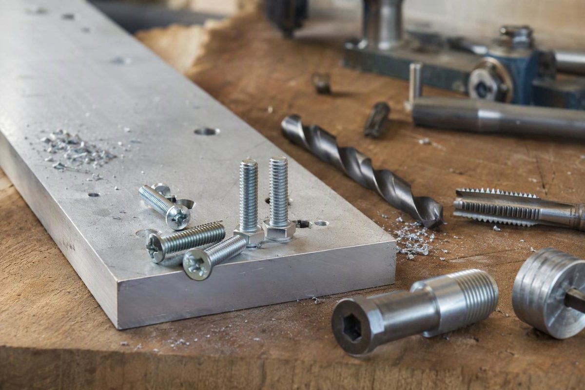
A #10 US machine screw has a nominal major diameter of 0.190 inch, equal to 4.826 mm—usually rounded to 4.83 mm. Measure across the outside crests of the threads, not across the head or down in the thread roots. Bolt Depot’s diameter chart lists this dimension for #10 screws.
That is the screw’s nominal diameter, not a clearance-hole or tap-drill recommendation.
Is #10 the same as 3/16 inch?
It is close, but not exact:
| Size | Diameter in inches | Diameter in millimeters |
|---|---|---|
| #10 screw, nominal | 0.1900 | 4.826 |
| 3/16 inch | 0.1875 | 4.7625 |
A 3/16-inch hole is nominally 0.0025 inch smaller than the #10 screw’s major diameter. Do not select a 3/16-inch drill as a clearance drill just because a chart gives that fraction as an approximate screw size. Bolt Depot labels it the nearest fractional size, not an exact equivalent.
Same diameter, two common machine-screw threads
Both 10-24 UNC and 10-32 UNF have a basic major diameter of 0.190 inch. The second number identifies threads per inch: 24 for the coarse thread and 32 for the fine thread. They require different mating threads and tap drills; diameter alone does not identify the screw. Carbide Depot’s UNC/UNF chart lists both.
For an unknown screw:
- Clean the threads and zero the caliper.
- Measure across the thread crests, keeping the jaws square to the screw’s axis. Repeat at several positions away from the tip.
- Use a thread-pitch gauge to distinguish 24 from 32 TPI.
- Check a known matching nut by hand. Stop if it binds; forcing it is not a thread-identification method.
Record the diameter and pitch separately. A caliper reading helps identify the size, but it does not verify the thread’s tolerance class. The measuring guide distinguishes major, shank and root diameters; keep those measurement locations separate. For other sizes and length-measurement guidance, use the US and metric screw size chart.
Choose the hole by its job
For a conventional #10 machine-screw joint, these are published reference choices. The cutting-tap rows below are approximately 75% thread recommendations for aluminum, brass and plastics, not universal choices for every material.
| Hole purpose | Thread | Drill | Nominal drill diameter |
|---|---|---|---|
| Clearance, close fit | 10-24 or 10-32 | #9 | 0.1960 in |
| Clearance, free fit | 10-24 or 10-32 | #7 | 0.2010 in |
| Before a cutting tap, approximately 75% thread | 10-24 | #25 | 0.1495 in |
| Before a cutting tap, approximately 75% thread | 10-32 | #21 | 0.1590 in |
LittleMachineShop’s tap and clearance chart supplies these values. It also lists larger drills for approximately 50% thread in steel, stainless and iron. Follow the tap maker’s recommendation for your material and tap type. Do not use these cutting-tap rows for forming taps; they need different hole dimensions, as shown in Jarvis’s forming-tap chart.
A clearance hole lets the screw pass through the upper part. A tap-drilled hole leaves material for the tap to cut the mating thread in the lower part. Before drilling finished stock, identify which job each hole must do. After drilling, deburr and check the actual fit—nominal bit diameter is not verification of the finished hole.
If the screw is a #10 wood screw or self-tapping screw, do not apply the machine-screw tap-drill rows. Select its pilot hole by screw design and parent material; see pilot-hole drill selection.