
6-32 Screw: Identify the Thread and Choose a Replacement
Identify a 6-32 machine screw, measure its length correctly, and match the head, material and usable thread engagement before ordering.
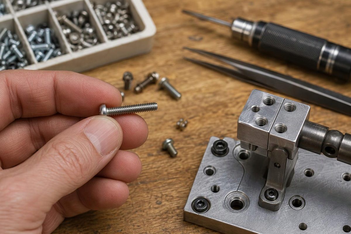
A 6-32 screw is a #6 machine screw with 32 threads per inch. Its nominal diameter across the thread crests is 0.138 inch (3.505 mm). The designation identifies the thread—not the screw length, head diameter or driver size. Machine screws fasten into a matching nut or tapped hole. Bolt Depot’s 6-32 product data confirms those dimensions and uses.
For a replacement, match more than the thread: check the length measurement, head seat, driver access and material before ordering.
Confirm an unknown screw
Clean the threads, then use these checks in order:
- Measure across the thread crests. Use a caliper across the outside of the threads, not across the head or down in the thread roots. Compare the reading with the #6 nominal diameter of 0.138 inch; do not treat the nominal figure as an exact acceptance limit for every finished screw. Bolt Depot’s diameter reference specifies this measurement location.
- Check the pitch. Place a 32-TPI thread-gauge leaf along several threads. Its teeth should nest without a progressively widening mismatch. Calculated from 32 TPI, adjacent crests are 0.03125 inch—or about 0.794 mm—apart.
- Try a known ordinary 6-32 nut by hand. It should advance without needing a driver. Stop if it binds; dirt, damaged threads or a mismatched pitch need investigation, not extra force. A locking nut is a poor identification aid because its locking feature deliberately adds resistance.
Diameter alone is not enough. A 6-40 fine-thread screw has the same nominal #6 diameter, but a different pitch; an 8-32 screw shares the 32-TPI pitch but has a larger diameter. Both distinctions appear in Fastenal’s coarse- and fine-thread tables.
Nor is 6-32 a metric designation. A common M3 machine screw is 3 mm in diameter with a 0.5 mm pitch. It is not an interchangeable substitute.
Measure length from the correct surface
In 6-32 × 1/2 inch, the final dimension is the screw’s nominal length. Where that measurement starts depends on the head:
| Head type | Measure length from |
|---|---|
| Pan, round or truss head | Underside of the head to the tip |
| Ordinary socket head cap screw | Underside of the head to the tip |
| Flat countersunk head | Top of the head to the tip, including the head |
| Oval countersunk head | Widest point of the head to the tip, excluding the raised crown |
These conventions are explained in Fastener SuperStore’s measuring guide.
For a new joint, assemble the actual plate, washers and spacers before choosing length. With an under-head-measured screw, subtract that stack thickness from the screw length to estimate how much reaches the nut or tapped part. Then check the available full threads, not just the distance to the screw tip.
For a blind tapped hole, leave clearance beneath the tip. A screw that bottoms can feel tight without clamping the plate. Do not assume the entire drilled depth contains usable thread or apply one engagement rule to steel, aluminum and plastic alike.
Match the head, drive and material separately
A pan head sits above the surface; a flat head needs a matching countersunk seat. Changing head style can therefore require changing the part—not merely buying another 6-32 screw. One conventional ASME B18.6.3 flat-head 6-32 screw has an 82-degree head angle. Check the selected product drawing rather than assuming every countersunk screw has that angle. See the countersink-and-drill guide if you need to make the seat.
The drive is another separate choice. The same cited screw uses a #2 Phillips driver: #6 thread size does not mean #6 driver size. Match the recess and check that the tool can reach it squarely in the assembled joint.
For an equipment replacement, retain the specified material, finish and strength unless a documented alternative is permitted. For a new build, specify those properties deliberately. “6-32” alone does not establish strength or corrosion suitability.
A complete order description might be “6-32 × 1/2 inch, Phillips pan head, zinc-plated steel,” with the required standard or strength specification added where relevant.
Check seating before final tightening
Start the screw by hand, bring the parts together, and confirm that the head bears properly, the tip clears and the threads engage as intended. If you need to create the threaded hole, use the separate 6-32 tap-drill guide; the screw’s outside diameter is not the tap-drill size.
There is no universal tightening torque for every 6-32 screw. Fastenal’s torque-tension guide separates recommendations by material, screw configuration and friction conditions, and warns that the mating nut or tapped hole must support the load. Follow the equipment or joint specification, including its lubrication conditions, and use an appropriately ranged torque tool when torque is specified. The bolt torque basics guide explains why thread size alone cannot set the tightening target.