
Socket Head Cap Screw: Identify It and Check the Seat
Identify a socket head cap screw, specify its standard and strength, and check head clearance, counterbore depth and seating before tightening.
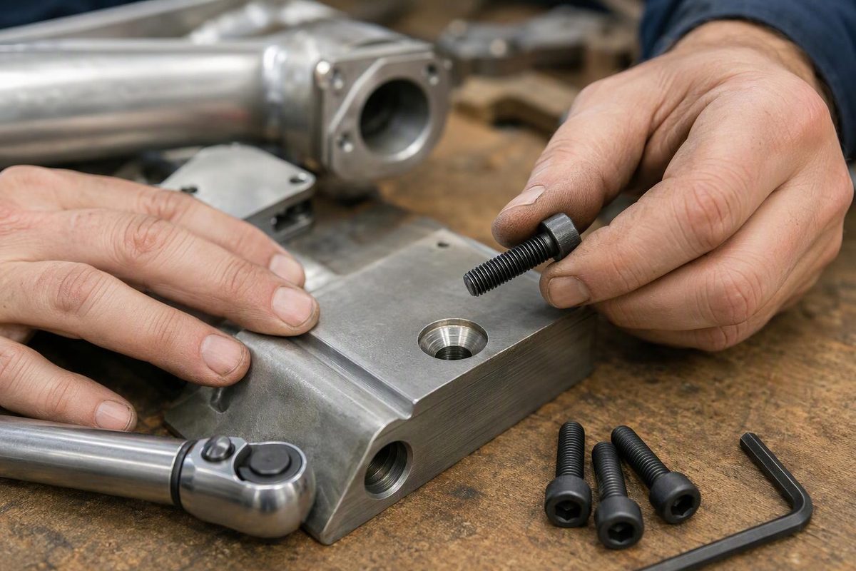
A standard hexagon socket head cap screw has a cylindrical head, an internal hex drive and machine threads. Its head bears on a flat surface; it can stand above the part or sit inside a flat-bottomed counterbore. The important fit check is not just whether the threads match—it is whether the head and under-head transition can seat properly.
Metric examples are commonly specified to ISO 4762. Suppliers also use the older DIN 912 designation; Bossard lists DIN 912 as withdrawn alongside ISO 4762 and identifies the head as cylindrical with a hexagon socket. Bossard product data
Identify the head, then measure the screw
“Allen screw” describes the drive loosely, not a complete fastener specification. A button head, countersunk head and headless set screw can also use a hex key. Do not order a replacement by key size alone.
Record these features:
- Thread diameter and pitch: measure across the thread crests and check pitch with a thread gauge.
- Length: measure from the flat bearing surface under the head to the end—not from the top of the head.
- Head diameter and height: needed for recess clearance and protrusion checks.
- Socket size: needed for the driver, not for identifying the thread.
- Threaded and unthreaded lengths: needed to check whether the screw can tighten through the actual clamped thickness.
Holo-Krome defines cap-screw length from the under-head bearing plane to the end. It separately defines grip length as the maximum distance from that bearing plane to the first complete thread: a clamped part thinner than that grip can prevent seating against a tapped mating part. Holo-Krome Technical Handbook, Tables 1–2
Example: M6 is not the head or key size
Westfield’s listed M6 × 30 Unbrako ISO 4762 screw has these dimensions:
| Feature | Listed dimension |
|---|---|
| Nominal thread diameter | M6 |
| Thread pitch | 1.00 mm |
| Maximum head diameter | 10.0 mm |
| Maximum head height | 6.0 mm |
| Hex key size | 5 mm |
Source: Westfield’s M6 product specification
These are fastener dimensions, not finished-hole dimensions. A recess must provide clearance around the head. Use the selected supplier’s drawing and tolerances before choosing a cutter, especially when replacing an unknown screw in an existing recess.
Specify geometry and strength separately
For inch socket head cap screws, ASME B18.3 defines dimensional characteristics; ASTM A574 specifies quenched-and-tempered alloy-steel screws and their mechanical requirements. They answer different questions: whether the screw fits, and what material and performance requirements it meets. Holo-Krome’s standards explanation; ASTM A574 scope
Likewise, ISO 4762 alone is not a strength class. Bossard’s cited product is class 8.8, while the M6 Unbrako example is listed as class 12.9. Do not infer strength from a black finish or the socket-head shape.
A useful metric order line would be:
Hexagon socket head cap screw, ISO 4762, M6 × 1.0 × 30 mm, alloy steel, property class 12.9, black oxide, fully threaded.
That is a specification example, not a recommendation that every M6 joint needs class 12.9. State material, class, finish and required thread coverage explicitly.
Give the head a flat, clear seat
To recess a cylindrical cap head, use a counterbore, not the conical seat used for a flat-head screw. Check four things before machining:
- Through-hole clearance: enough for the shank and expected hole-position variation.
- Counterbore diameter: clearance around the maximum head envelope, including any washer that will sit inside it.
- Depth and remaining stock: enough for the intended head position, including washer thickness if used, without leaving an inadequately thin bearing section.
- Under-head fillet clearance: the rounded head-to-shank transition must not ride on a sharp hole edge.
For an inch reference, Holo-Krome’s Table 5 lists a 9/32-inch normal-fit clearance hole and a 7/16-inch counterbore diameter for a 1/4-inch 1960-series socket head cap screw. Those are different holes serving different purposes; neither is a tap-drill size. Holo-Krome drill and counterbore table
Deburr the seat and provide only the edge relief needed to clear the fillet. Holo-Krome warns that an interfering edge can prevent seating or damage the fillet, while excessive chamfering reduces bearing area. Do not turn a small clearance chamfer into a countersink. Holo-Krome Table 5, chamfering notes
Check the finished joint before tightening
After machining, measure the recess diameter and depth, then trial-fit the actual screw. Confirm that the head bears on the flat seat rather than binding against the recess wall or fillet edge.
Recheck screw length after recessing the head: a deeper counterbore reduces the thickness beneath the head and lets the same screw reach farther into the mating part. In a blind tapped hole, verify usable full-thread depth and clearance below the screw tip. A screw stopping at the bottom is not evidence that the joint is clamped.
Finally, confirm that the driver can engage fully in the assembled position. Use the specified tightening torque for the actual screw, joint material and thread condition—not a value chosen from socket size. Holo-Krome treats torque as application-dependent, including lubrication and joint design. Holo-Krome application guidance For friction and tightening sequence, see bolt torque basics.