
#8 Screw Diameter: 0.164 Inch, Not the Hole Size
A #8 machine screw is nominally 0.164 inch (4.17 mm) across the threads. Check pitch, then choose a clearance hole, tap drill or pilot hole.
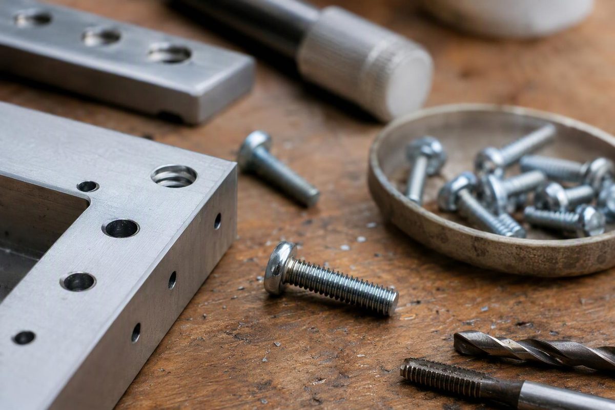
A #8 machine screw has a nominal major diameter of 0.164 inch, equal to 4.1656 mm, usually rounded to 4.17 mm. Major diameter means the outside diameter across the thread crests—not the head diameter or the diameter down in the thread roots. LittleMachineShop’s reference chart lists that diameter for both 8-32 and 8-36 threads.
The number #8 is a screw-size designation, not an eighth of an inch and not a drill-bit number. Do not drill a 0.164-inch hole simply because the drawing calls for a #8 screw: the hole size depends on what the screw must do there.
Identify the thread before matching a nut or tap
These two #8 machine threads share the same nominal outside diameter:
| Thread designation | Nominal major diameter | Threads per inch |
|---|---|---|
| 8-32 UNC, coarse | 0.164 in. | 32 |
| 8-36 UNF, fine | 0.164 in. | 36 |
American Fastener’s chart identifies 8-32 as coarse and 8-36 as fine. They need different matching nuts and taps, even though their outside diameters are the same.
For a loose screw, clean the threads and measure across the crests with the caliper’s outside jaws, away from the point or damaged end threads. Repeat the reading at another position. Treat a reading near 0.164 inch as an identification clue—not proof of the complete thread specification or compliance with a tolerance.
Check pitch with a thread gauge, then try a known matching nut by hand. Stop if it binds; forcing it is not a useful identification test. A diameter reading alone also cannot establish that a screw is metric or inch-series.
Choose the hole by its job
For a #8 machine screw, these are useful reference sizes:
| Hole’s job | Reference drill | Nominal drill diameter |
|---|---|---|
| Screw passes through, close clearance | #18 | 0.1695 in. |
| Screw passes through, free clearance | #16 | 0.1770 in. |
| Hole is cut with an 8-32 cutting tap | #29 | 0.1360 in. |
The clearance sizes come from LittleMachineShop’s chart. Its #29 tap-drill entry is in the 75% thread column for aluminum, brass and plastics; American Fastener also lists #29 for 8-32. These are reference selections, not substitutes for a specified finished-hole tolerance or the tap maker’s instructions. Forming taps require their own hole recommendation: for example, Grainger’s listing for OSG forming tap 1400114908 specifies a #25 drill, not #29.
On a bracket screwed to a tapped plate, the bracket gets the clearance hole; the plate gets the smaller tap-drill hole followed by tapping. For the tapping sequence, see the 8-32 drill and tap guide.
A wood or self-tapping screw needs a pilot selected for its particular screw design and parent material—not the machine-screw tap drill above. Use the pilot-hole guide for that separate decision.
Before assembling finished parts, deburr the holes and check the actual screw’s fit. A nominal drill size is the tool selection; the finished hole and mating thread are what must work.