
Tap and Die Set: Choose the Tools and Cut Straight Threads
Choose a tap and die set by thread, material and hole type, then prepare, cut and inspect internal and external threads without forcing the tools.
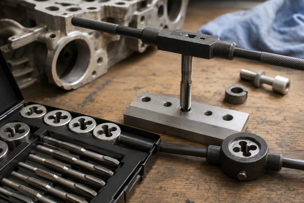
Choose a tap and die set by its actual thread sizes, pitches and material ratings—not its piece count. A cutting tap makes an internal thread in a prepared hole; a die cuts an external thread on a rod. The useful set is the one that matches your fasteners and includes holders you can control in the available space.
For a builder mainly making threaded holes in brackets and plates, individual taps, matching drills and a good tap wrench may be a better first purchase than a large combination set. Add dies when you need to thread raw rod or make custom studs.
What to check before buying
Make a short list of the threads your build uses, then compare it with the set’s contents.
- Full thread designation: Match the thread system, diameter, pitch and hand. “Metric” or “SAE” on the case is not enough; check each required size and its coarse or fine pitch.
- Cutting-tool material: High-speed steel (HSS) is a sensible starting point for making new threads in common engineering metals. Check the particular tool’s rating for steel, aluminium or brass; stainless may warrant a more specialised tool. RUKO’s hand-tap guidance distinguishes general HSS applications from more demanding work using HSS-Co 5.
- Tap styles: Check whether each size has only one tap or includes a short-chamfer option for blind holes.
- Holders: Confirm the tap wrench grips the tap’s square shank and the die stock accepts the supplied dies. Check handle clearance around your workpiece.
- Supporting tools: Budget for the correct tap drills, a pitch gauge, measuring tools, cutting lubricant suitable for the material, and secure workholding. Do not assume the kit includes them.
Read mixed-tool descriptions carefully. An “HSS drill and tap” package need not contain an HSS tap: IRWIN’s 80221 combination explicitly pairs an HSS drill with a high-carbon-steel tap.
Cutting tools are not thread restorers
For dirty or lightly nicked existing threads, choose a matching thread chaser or restorer rather than automatically running a cutting tap or die through them. Lang’s restorer instructions describe removing nicks and burrs without undercutting good threads and explicitly say not to use these tools to cut new threads. Lang thread-restorer catalogue
Neither tool puts missing metal back into a stripped hole. For substantial damage, assess replacement or a suitable thread insert for metal. Do not treat easier screw assembly as proof that a damaged load-bearing thread is sound.
Choose the tap for the hole
For conventional straight-flute hand taps, the familiar U.S. names describe the lead-in chamfer:
| Style | Typical chamfer | Practical role |
|---|---|---|
| Taper | About nine threads | Easier starting where there is room for the long lead |
| Plug | About four threads | General-purpose compromise between starting and depth |
| Bottoming | One or two threads | Extending full threads closer to a blind-hole bottom |
These are approximate lengths; inspect the actual tool. Travers explains the chamfer styles and also distinguishes spiral-point taps, which push chips ahead for through-holes, from spiral-flute taps, which draw chips out of blind holes in suitable long-chipping materials.
Drilled depth is not full-thread depth. A blind hole needs room beyond the required full threads for the tap’s lead and chip clearance. Even a bottoming tap has a lead; do not use contact with the hole bottom as your stopping method. Select the tool and plan its travel before cutting. Guhring’s technical catalogue makes blind-hole suitability of its D-chamfer taps conditional on enough tap-drill depth to accommodate the chamfer.
Cut an internal thread by hand
This sequence is for a conventional right-hand, straight-flute cutting tap, not an NPT, forming or insert tap. Wear eye protection during drilling, chip clearing and threading.
- Confirm the thread and drill recommendation. Use the tool maker’s chart for the actual tap. For a quarter-inch job, first identify the tap’s complete marking.
- Clamp and drill. Locate the hole, secure the workpiece, and drill on the intended axis. Check the finished hole against the required diameter and depth; the marking on the bit is only the nominal tool size.
- Deburr and clean. Make an appropriate entrance chamfer and remove chips.
- Start aligned. Grip the tap securely in the correct-size wrench. Apply suitable cutting lubricant and align the tap with the hole axis using a suitable guide. For a hole perpendicular to a flat face, check from two directions with a square. Do not start tilted and try to straighten it after it has cut.
- Advance with control. Periodically reverse enough to break the chip, following the maker’s instructions. Stop if resistance rises sharply; withdraw carefully and check chips, lubrication, alignment and depth rather than adding leverage.
- Finish to the planned depth. Where needed, follow with the appropriate shorter-chamfer tap in the established thread. For staged hand-tap sets, follow the manufacturer’s specified order. Back the tap out carefully when finished.
RUKO’s internal-thread procedure supports entrance preparation, square alignment, lubrication and chip-breaking. Do not transfer a hand-tap reversal routine blindly to specialised tapping tools.
Cut an external thread with a die
Measure the rod before starting. Prepare its diameter to the die maker’s recommendation and the required thread limits; nominal stock size alone does not establish a suitable blank.
Chamfer the rod end, clamp it securely, and fasten the die in its stock with the lead-in side facing the rod. Tameson’s die instructions identify the chamfered side as the entry side.
Keep the die aligned with the rod axis, lubricate, and turn steadily. Reverse periodically for chip-breaking as instructed. If it starts crooked or binds, stop and investigate rather than forcing it farther. Back the die off when the required thread length is cut. RUKO’s external-thread guide covers blank preparation, chamfering, workholding and chip control.
Inspect before assembly
Clean away chips and inspect for torn threads, burrs and an off-axis start. Try a known matching screw or nut by hand through the intended engagement. In a blind hole, verify that the screw can seat the joint without bottoming first.
A mating fastener is a useful assembly check, not proof of the specified thread tolerance or joint strength. Where the drawing requires verified thread limits, use the appropriate thread gauges and acceptance procedure; VÖLKEL describes GO/NO-GO inspection for internal threads.
Before final tightening, remove cutting residue and establish the thread condition required by the assembly specification. Cutting lubricant should not become an unplanned change to the joint’s torque and lubrication conditions.