
Drill and Tap Bit: Choose by Thread, Material and Thickness
Choose a combined drill and tap bit by thread, material, stock thickness and exit clearance, then cut and check the finished threaded hole.
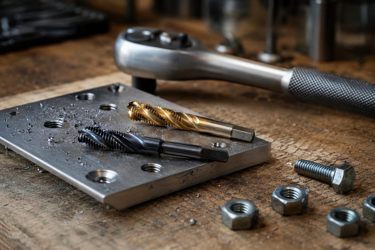
A combined drill and tap bit makes the tap-size hole and cuts its internal thread with one tool. Many hex-shank versions also have a deburring/countersinking section behind the tap. That saves tool changes, but it does not make the bit suitable for every thickness, material or hole depth. Greenlee’s drill/tap data sheet describes those separate cutting sections.
For garage fabrication, consider one for repeated through holes in material within the bit’s stated capacity. For blind holes, stock beyond that capacity, or jobs requiring independent control of drilling and tapping, choose separate tools.
Check four things before buying
1. Match the complete thread marking. Buy a 10-24 bit for a 10-24 screw—not merely a “#10” bit. Klein’s 32217 kit, for example, includes separate 10-24 and 10-32 tools. Its 1/4-inch hex shank describes the drive connection, not the thread it cuts; the kit contains several thread sizes on that connection. Klein’s sell sheet identifies both.
2. Check the work material. “For metal” is not enough. Klein lists aluminum, brass, copper, plastic and mild steel for that kit. Do not extend that list to stainless or hardened steel without approval for the particular bit. A coating or an HSS marking alone is not a material-capacity specification. Klein’s product page gives the intended applications.
3. Measure the thickness being threaded. Capacity is model-specific. Klein rates its kit for up to 10-gauge metal; Greenlee’s March 2013 manual for the LDTAP8-32, LDTAP10-32 and LDTAP1/4-20 long bits provides procedures for material up to 1/2 inch thick. Those are different tools, not interchangeable limits. Measure your stock and compare it with the exact bit’s instructions; do not treat gauge as a universal inch measurement. Klein specifications and Greenlee long-bit manual.
4. Check the space behind the hole. A drill tip remains ahead of the tapping section. Allow room for it to project beyond the work while the tap completes the thread. Check the opposite wall of tubing, backing plates and anything inside an enclosure—not just the thickness of the first wall. Through-hole suitability is a real selection limit: Victor Machinery specifies through holes for its coarse-thread combined drills and taps. Victor’s tool listing. Do not use the tool near live circuits, as the Greenlee manual warns.
For a blind hole, a separate drill and suitable tap let you plan drill depth and usable thread depth independently. Use the tap and die set guide for that route rather than trying to make a through-hole combination bit reach the bottom.
Cut without forcing the transition
Try the process on scrap of the same material and thickness before drilling the finished bracket or plate.
- Secure the work and mark the hole. Clamp small stock; never hold it in one hand while drilling with the other. Wear eye protection. Seat the bit securely with the drill’s power disconnected. These precautions follow CCOHS guidance for powered hand drills.
- Use the specified drive and cutting fluid. A reversible drill-driver is the setup described in Greenlee’s long-bit manual. Use an impact driver only when the particular bit’s manufacturer approves it—not merely because the hex shank fits. Apply the manufacturer-recommended cutting lubricant.
- Keep the bit square to the surface. Maintain the same axis as the drill section enters and the tap follows. Do not try to correct an angled hole by levering the drill sideways.
- Follow the bit’s feed and chip-clearing procedure. “One tool” does not always mean one uninterrupted pass. Greenlee’s long-bit manual calls for an intermediate reverse-and-clear step in its thicker-material range. Follow your model’s speed instructions rather than assuming one RPM suits every combination bit.
- Control any deburring section, then reverse out. If the bit includes that section, do not continue feeding merely to make a larger chamfer. Reverse rotation to withdraw through the new thread; do not pull the engaged tap straight out. Stop the tool before cleaning chips for the next hole. The lubricant, chip-clearing and reverse-withdrawal sequence is documented in the Greenlee manual.
If the bit jams, stop rather than repeatedly pulsing the trigger. Disconnect power before dealing with it, as CCOHS advises.
Check the finished thread, not just the label
Clean the hole and inspect both faces for burrs, torn threads and excessive chamfering. Start a clean, known-correct screw by hand and check that it travels through the intended engagement without binding. That is a useful fit check, not proof of thread tolerance or joint strength; use the specified thread gauge where tolerance acceptance matters.
A bit’s maximum stock thickness is a cutting limit, not a minimum safe thread engagement. If the plate provides too little engagement for the load, changing to a combination bit does not solve the joint design.