
1/8 NPT Tap Drill Size by Tap Maker
R measures 0.3390 inch and is the most frequent commercial pairing in the sources checked; other published charts specify Q at 0.3320 inch.
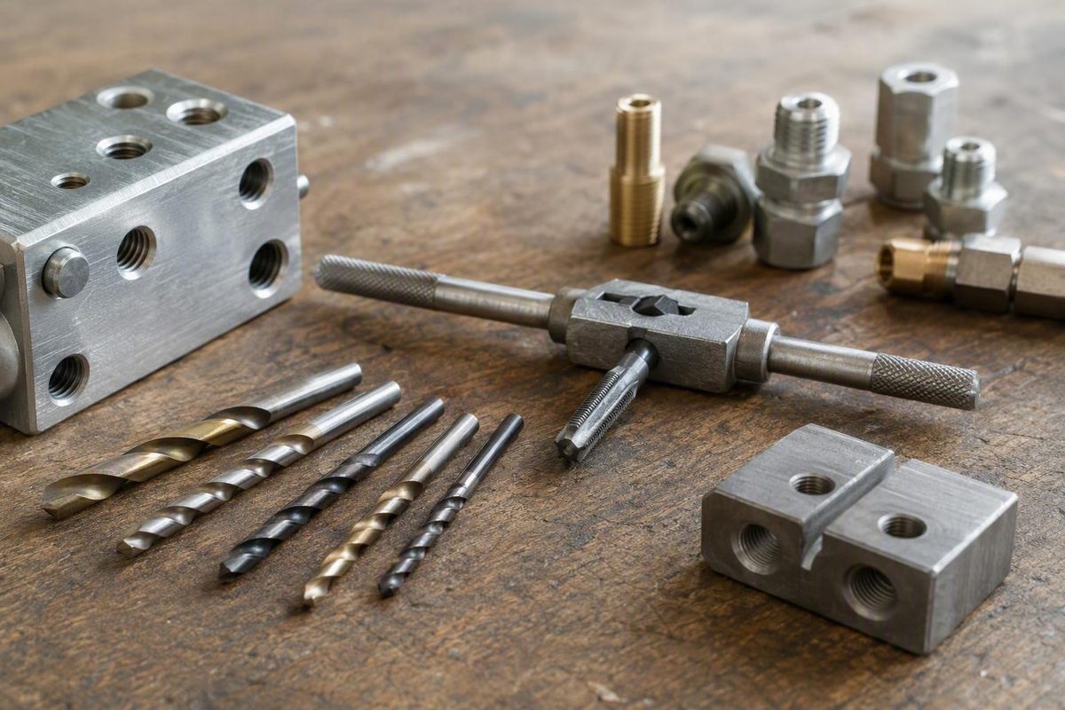
The short answer: check the tap maker, then choose between Q and R
Use the drill size specified by the manufacturer of your exact tap. If you bought a matched tap-and-drill kit, use the drill supplied with that kit unless the component instructions call for a different preparation method.
If you need the common shop answer, expect to encounter two recommendations:
- Letter R: 0.3390 inch, approximately 8.61 mm. R is the most frequent commercial pairing among the supplied sources. The Sensor Connection, for example, supplies an R drill with its 1/8-27 NPT tap and identifies the drill as 0.339 inch.1
- Letter Q: 0.3320 inch, approximately 8.43 mm. Other published charts specify Q for the same thread. MISUMI lists 1/8 NPT at 27 threads per inch with a 0.332-inch Q drill.2
Neither size can be declared universally correct from the available evidence. The sources conflict, and no supplied primary standards document resolves that conflict for every tap geometry and hole-preparation method. Product listings establish what particular manufacturers or sellers pair with their taps; they do not establish a universal rule.
Use this decision sequence:
- Read the markings on the tap and confirm that it is 1/8-27 NPT.
- Follow the exact tap manufacturer’s current drill recommendation.
- Use the drill supplied with a matched kit unless the component instructions override it.
- Determine whether the documented process includes a tapered pipe reamer.
- If authoritative instructions remain unavailable, recognize Q as the smaller published recommendation and R as the more frequent commercial pairing in the supplied sources.
- For noncritical work, test the setup in comparable scrap before modifying an expensive part.
The difference between Q and R is only 0.007 inch, calculated from their published diameters, but it changes how much material the cutting tap must remove.3 Drill diameter is also only one part of the operation. The tap must be started squarely, chips must be cleared, and the final depth must suit the intended fitting.
Pressure-bearing or leak-critical work: For a fuel, gas, brake, hydraulic, compressed-air, or similarly consequential system, do not select the tooling from a generic online chart alone. Consult the tap, fitting, and component manufacturers for the approved preparation and installation procedure before cutting the port.
Quick-reference size table: Q, R, 21/64, and 11/32
These four sizes are close, but they are not interchangeable designations.
| Drill size | Decimal diameter | Approximate metric diameter | How to treat it |
|---|---|---|---|
| 21/64 inch | 0.3281 in3 | 8.33 mm | Smaller than Q; supplied in at least one commercial 1/8-27 NPT set |
| Letter Q | 0.3320 in3 | 8.43 mm | Smaller of the two published letter-drill recommendations |
| Letter R | 0.3390 in3 | 8.61 mm | Most frequent commercial pairing among the supplied sources |
| 11/32 inch | 0.34375 in4 | 8.73 mm | Common fractional alternative, but not an exact equivalent to R |
Comparing the four sizes
A 21/64-inch drill is 0.328125 inch by calculation, normally rounded to 0.3281 inch. It is about 0.0039 inch smaller than Q. At least one commercial set supplies this drill with a 1/8-27 NPT tap, demonstrating that it is an actual product pairing rather than merely a nearby fractional size.5
A WeldingWeb participant also attributed 21/64 inch to preparation followed by a tapered pipe reamer. That statement was presented as a report from Machinery’s Handbook, but the handbook passage itself was not supplied and therefore cannot be treated here as verified primary evidence.6 Use 21/64 inch when the exact kit or documented process specifies it, not because every hole drilled to that size necessarily requires the same next step.
A Q drill is 0.3320 inch. It is the smaller of the two conflicting letter-drill recommendations and leaves more material in the developing thread profile for the cutting tap to remove.3
An R drill is 0.3390 inch, or 0.007 inch larger than Q. It appears in several commercial charts and matched kits, making it the most frequent commercial pairing in the supplied evidence—not a universal standard.1
An 11/32-inch drill is 0.34375 inch, often rounded to 0.3438 inch. It is approximately 0.00475 inch larger than R, so it must not be described as an R drill. Informal shop discussions sometimes present it as a practical fractional alternative, but that does not make it interchangeable with the specified letter size.4
The size order is:
21/64 < Q < R < 11/32
What changing the hole size does
A smaller starting hole leaves more material in the thread profile for the cutting tap to remove.
A larger starting hole generally reduces the amount of material the tap must cut. The corresponding tradeoff is that less material remains in the resulting thread profile. This does not prove that a particular port will leak or establish a specific percentage of thread engagement; it explains why moving to a larger drill is not a neutral substitution.
For ordinary, noncritical work, a tap manufacturer may approve a nearby fractional alternative. For critical work, convenience should not override the documented preparation for the tap and component.
Why a 1/8-inch NPT thread does not use a 1/8-inch drill
The 1/8 in 1/8 NPT is a nominal pipe-size designation. It is not the thread’s outside diameter and is not an instruction to drill a 0.125-inch hole.
The thread discussed here is 1/8-27 NPT, which the cited charts associate with 27 threads per inch.2 Its published starting-hole recommendations cluster around one-third of an inch, which is why Q, R, 21/64, and 11/32 are all much larger than 1/8 inch.
This naming convention can be counterintuitive if most of your experience is with ordinary machine-screw threads. Reading the nominal pipe label as the required pilot diameter would produce a hole far outside the published recommendations discussed here.
NPT is a tapered pipe thread. As the tapered tap advances, progressively more of its cutting portion engages the work. That is why turning resistance normally increases as the tap goes deeper. In an aluminum-casting example discussed by Garage Journal users, the tap became progressively harder to turn after its first few threads; the discussion emphasized checking depth and not automatically running the tapered tap through the entire hole.8
Keep two dimensions separate:
- Pilot-hole diameter controls the starting opening and how much material the tap must cut.
- Tapping depth controls how far the mating tapered fitting can enter before engagement becomes tight.
Choosing the specified drill does not determine final fit by itself. The hole can still be tapped too deeply or started out of line.
Do not improvise with guesses such as 1/8 inch, 3/32 inch, or 7/32 inch. Those values fall outside the published Q, R, 21/64, and 11/32 options supported by the available evidence.
Why tap-drill charts disagree about letter Q and letter R
The disagreement is genuine rather than a single isolated transcription error.
Several commercial sources pair a 1/8 NPT tap with an R drill. Drill America sells a matched 1/8 NPT tap-and-R-drill kit, while The Sensor Connection identifies the R drill in its 1/8-27 NPT kit as 0.339 inch.7 These products establish R as a common commercial pairing.
Other technical and vendor charts specify Q. MISUMI’s chart lists a 0.332-inch Q drill for 1/8 NPT, while 6G Tools also lists Q at 0.3320 inch for 1/8-27 NPT.2 Q is therefore a published recommendation, not an improvised substitute.
The supported conclusions are limited:
- R is the most frequent commercial pairing among the supplied sources.
- Q is also a published recommendation for 1/8-27 NPT.
- A matched kit establishes the intended pairing for that kit, not for every NPT tap.
- The available evidence consists mainly of vendor charts, product listings, and forum discussions rather than a supplied primary standard.
One WeldingWeb participant attributed a more detailed distinction to Machinery’s Handbook: Q for direct tapping of a tapered thread, 21/64 inch before tapered reaming, and R for a straight pipe thread.6 That may help explain why different figures circulate, but the handbook page was not provided. The statement must therefore remain a secondary report, not a verified handbook rule.
Possible questions behind apparently conflicting charts include:
- Does the procedure call for direct drilling and tapping or for a tapered pipe reamer?
- What geometry does the exact tap use?
- Is the tap marked NPT, NPTF, or for a straight pipe thread?
- Is the listed drill a preferred size or an acceptable alternative?
- Does the toolmaker provide different instructions for a particular material or production method?
These are questions to investigate, not proven explanations for every Q-versus-R difference. Commercial products explicitly pair R drills with taps labeled NPT, so it would be incorrect to claim that all R recommendations apply only to straight pipe threads or NPTF.
Before selecting the drill, clean the tap and read its markings. Confirm 1/8-27 NPT, identify the manufacturer, and look for its current packaging, catalog entry, chart, or technical guidance. Do not transfer a recommendation from another pipe-thread form merely because the nominal size matches.
If the manufacturer cannot be identified, determine whether the documented process calls for a reamer and limit any scrap testing to noncritical work. A trial can reveal whether the setup is practical, but it does not certify pressure integrity.
How to drill and start the tap squarely
Begin by confirming that the workpiece is suitable for the intended port. Check the available material at the location and make sure drilling will not interfere with another feature. The supplied evidence does not establish one universal minimum wall thickness for every material and application.
For its sensor-fitting installation, The Sensor Connection gives approximately 1/4 inch or greater as general wall-thickness guidance.1 That figure belongs to the vendor’s application and should not be treated as a universal minimum for all 1/8 NPT ports.
1. Secure and locate the work
Hold the workpiece securely and locate the center accurately. If the proposed surface does not provide a reliable drilling reference, use a suitable fixture or preparation method rather than expecting the drill to establish alignment on its own.
Plan how chips will be removed and how the part will be cleaned after machining. Follow the component manufacturer’s instructions where internal cleanliness is consequential.
2. Drill perpendicular to the surface
The Sensor Connection’s installation guidance calls for drilling perpendicular to the surface, using cutting fluid, and clearing chips and burrs.1 A drill press, mill, guide, or suitable fixture may help maintain alignment, provided the setup itself is correctly positioned.
If drilling by hand, check alignment from two directions. The drilled hole establishes the path from which the tap must start.
3. Deburr and clean the entrance
Remove the entrance burr without unnecessarily enlarging the hole. Clear loose chips before introducing the tap.
For a blind hole, clean the hole without compacting chips at the bottom. For a through-hole, account for the burr at the drill’s exit.
4. Use suitable cutting fluid
Use cutting fluid appropriate to the work material, tap, and toolmaker’s directions. The available evidence supports using cutting fluid but does not establish one fluid as suitable for every material or tap.1
Lubrication does not correct an incorrectly sized hole or a tap started out of line. If resistance becomes abrupt or severe, stop rather than trying to overcome it with leverage alone.
5. Start the tap in line with the hole
Use a proper tap wrench where access permits. Apply balanced force and check alignment from two perpendicular directions during the first turns.
Garage Journal contributors discussing a restricted-access installation cautioned that socket-driven or improvised arrangements can make it harder to hold the tap straight.8 If limited access requires such an arrangement, pay particular attention to alignment and avoid treating the added leverage as permission to force the tap.
6. Advance gradually and clear chips
Cut a short distance, then reverse or withdraw as appropriate for the tap and material to clear chips. Follow the tap maker’s instructions when it specifies a particular technique.
As resistance rises:
- Stop advancing.
- Back the tap out as needed.
- Clear the flutes and hole.
- Reapply the specified cutting fluid.
- Recheck alignment and depth.
Do not rely on one fixed forward-and-reverse formula for every tap design and work material.
7. Allow for blind-hole clearance
Obtain the required hole-depth and clearance information from the toolmaker rather than applying an unsupported universal formula.
The tapered thread also should not automatically be cut to the bottom of the drilled hole. Stop according to the required fitting engagement or specified inspection method.
When the finished component is expensive or difficult to replace, reproducing the operation in scrap of similar material and thickness is prudent for noncritical work. It can reveal setup and depth-control problems, but it is not a substitute for the approved procedure in a consequential application.
Control thread fit by depth, not by running the tap through
The supplied evidence does not support one fixed number of turns or one universal tapping depth for every 1/8 NPT port.
Because the tap is tapered, progressively more of it engages the work as it advances. A gradual increase in resistance is therefore expected. Garage Journal and Turbo Diesel Register discussions both emphasize checking the intended fitting and avoiding excessive tapping depth.84
For ordinary, noncritical shop work:
- Start the tap squarely.
- Cut a short distance.
- Reverse or withdraw as needed to clear chips.
- Remove and clean the tap.
- Clean the hole.
- Check the actual fitting intended for the port.
- Repeat in small increments until the required engagement is reached.
Use the intended fitting, not an unrelated plug that merely has the same nominal thread. If the application provides a specified gauge or inspection procedure, use that procedure instead of treating hand fit as the final standard.
Running a tapered tap too deeply allows the fitting to advance farther before it tightens and may leave the final fit too loose. Informal reports addressing 1/8 NPT repeatedly caution against treating the pipe tap like a conventional straight tap and automatically running it through the work.4
A through-hole does not alter that principle. “Through-hole” describes the drilled opening; it does not define the correct endpoint of the tapered thread.
Progressive test-fitting is a practical check for noncritical shop work, but it does not prove that a port is leak-free or suitable for pressure service. Obtain the required fitting and component instructions when failure would have serious consequences.
Material, wall thickness, and pressure change the stakes
Material, wall thickness, access, tap construction, and the required fit can all affect tool selection and tapping effort. The supplied evidence does not establish a universal material-by-material drill-size table, so the exact toolmaker’s guidance remains the priority.
Aluminum and other softer materials
One Garage Journal user drilled an 11/32-inch hole in a 1/2-inch-thick aluminum casting and reported that the tapered tap became progressively harder to turn. The user later completed the port after adjusting technique and final depth.8
That is an individual shop account, not proof that 11/32 inch is correct for every aluminum casting. It is most useful as an example of why increased resistance does not by itself determine whether the starting hole was wrong—and why tapping depth must be checked as the work proceeds.
Mild steel and cast iron
The Sensor Connection describes the carbon-steel tap in its kit as suitable for mild steel, cast iron, cast aluminum, and ductile iron.1 That statement applies to the vendor’s product. It should not be generalized to every carbon-steel tap or every workpiece with the same broad material label.
Use a tap approved by its manufacturer for the actual material.
Stainless steel
For stainless steel, the same vendor recommends a cobalt or coated tap rather than the carbon-steel tap included in its kit.1 This is product-specific vendor guidance, not a universal classification of every stainless alloy or tapping tool.
If the tap maker does not approve the tool for the work material, change the tooling rather than attempting to compensate with an undocumented drill size.
Thin-wall tubing
For its sensor application, The Sensor Connection recommends a weld bung instead of directly tapping thin-wall tubing.1 That recommendation should remain within its stated context.
The appropriate method for another thin-wall installation must come from the relevant component and fitting instructions. The available evidence does not establish that every thin-wall application requires the same bung or joining method.
Pressure-bearing systems
Fuel, gas, brake, hydraulic, compressed-air, and similar systems carry consequences beyond whether the tap can physically cut the hole.
Before modifying such a component, consult the tap, fitting, and component manufacturers to confirm that the component may be modified and to obtain the approved drilling, tapping, inspection, and installation procedure. Do not infer pressure suitability from drill size or hand fit alone.
No Q, R, 21/64-inch, or 11/32-inch drill guarantees a seal, pressure rating, or compliant installation. The available sources establish candidate hole sizes and selected commercial pairings; they do not certify a finished pressure-bearing port.
Common mistakes and a final pre-drill checklist
Before drilling, verify the following:
- [ ] The tap is marked 1/8-27 NPT.
- [ ] The tool is not NPTF or a straight pipe-thread tap.
- [ ] You have found the exact tap manufacturer’s drill recommendation.
- [ ] If using a matched kit, the drill belongs with that tap.
- [ ] You know whether the process includes a tapered pipe reamer.
- [ ] The tap manufacturer approves the tool for the work material.
- [ ] The component has suitable material at the proposed location.
- [ ] You know whether the hole is through or blind.
- [ ] A blind hole has adequate drilled depth, tap-lead clearance, and chip space according to the toolmaker.
- [ ] The drill and tap can be held square to the surface.
- [ ] Chips and burrs can be removed as required by the component instructions.
- [ ] The intended mating fitting is available for the specified fit check.
- [ ] The system has been identified as ordinary, leak-critical, pressure-bearing, or otherwise consequential.
- [ ] Manufacturer guidance will be obtained before modifying a critical component.
Do not use a 1/8-inch drill simply because the thread is called 1/8 NPT. The number is a nominal pipe-size designation, not the pilot-hole diameter.
A 3/8-inch drill is 0.375 inch, making it substantially larger than Q, R, 21/64, and 11/32. It is outside all supported candidate recommendations in this article. A Supra Forums discussion addressing this proposed substitution likewise identifies 3/8 inch as too large for the stated 1/8 NPT job.9
A 7/16-inch drill is also outside the relevant range. The supplied commercial NPT charts associate 7/16 inch with 1/4 NPT, not 1/8 NPT.7 If a package combines a 1/8 NPT tap with a 7/16-inch drill, stop and verify the labeling.
Do not call 11/32 inch an R drill. The sizes are 0.34375 and 0.3390 inch respectively, a difference of approximately 0.00475 inch.4
Finally, do not force the tap simply because tapered tapping becomes harder as the tool advances. A gradual rise in resistance is expected; abrupt or severe resistance calls for stopping, clearing the tool, and checking the setup against the tap maker’s instructions.
The compact workflow is:
Identify the exact thread → read the exact tap instructions → select the specified drill → prepare the hole squarely → tap incrementally → check the intended fitting or specified gauge → obtain manufacturer verification for critical service.
The conditional answer is more useful than a false universal rule: use the drill specified for your exact tap. Expect to find R at 0.3390 inch as the most frequent commercial pairing among the supplied sources and Q at 0.3320 inch on other published charts.3 Treat 21/64 inch and 11/32 inch as distinct alternatives, keep the tap square, and control the final fit by tapping depth rather than by running the tool fully through.
Frequently asked questions
Is a letter Q or letter R drill better for a 1/8-27 NPT tap?
Neither is universally better. Use the size specified by the exact tap manufacturer.
Q measures 0.3320 inch, while R measures 0.3390 inch.3 Q is the smaller published recommendation; R is the more frequent commercial pairing among the supplied sources. A matched kit establishes the appropriate pairing for that kit.
Can I use an 11/32-inch drill instead of a letter R bit?
Only when the tap manufacturer permits the substitution or when it is acceptable for the particular noncritical job.
An R drill is 0.3390 inch, while 11/32 inch is 0.34375 inch, making the fractional drill approximately 0.00475 inch larger.4 They are close, but they are not equivalent.
When is a 21/64-inch drill used for 1/8 NPT?
Use 21/64 inch when the matched kit or documented preparation method specifies it. The size is approximately 0.3281 inch and appears in at least one commercial 1/8-27 NPT tap-and-drill set.5
A secondary forum report also associates it with preparation followed by a tapered pipe reamer, but the underlying handbook passage was not supplied and has not been directly verified.6
How deep should a 1/8 NPT tap be run?
There is no supported universal number of turns or fixed depth. Advance incrementally, clear the chips, and check the intended fitting or the inspection method specified by the manufacturer.
Do not automatically run the tap through a through-hole. Cutting too deeply can allow the tapered fitting to enter farther before it tightens.8
Why does a 1/8 NPT tap become harder to turn as it advances?
NPT is tapered, so progressively more of the tap engages the work as it advances. A smooth increase in resistance is expected.8
If resistance becomes abrupt or severe, stop. Withdraw and clean the tap, clear the hole, verify alignment and pilot-hole size, and check whether the required thread depth has already been reached. Do not use added leverage as a substitute for identifying the cause.
-
The Sensor Connection’s 1/8-27 NPT drill-and-tap kit and installation guidance ↩↩↩↩↩↩↩↩
-
Turbo Diesel Register discussion of R, 11/32 inch, and tapered-thread depth ↩↩↩↩↩↩
-
WeldingWeb discussion of Q, R, 21/64 inch, and reamed preparation ↩↩↩
-
Garage Journal discussion of tapping depth in an aluminum casting ↩↩↩↩↩↩
-
Supra Forums discussion comparing R, 11/32 inch, and 3/8 inch ↩