
Using Clamp Pins for a Datum: Locate First, Clamp Second
Use fixed pin contacts to establish a repeatable jig reference, then check seating, clamp movement and reload variation before drilling or layout.
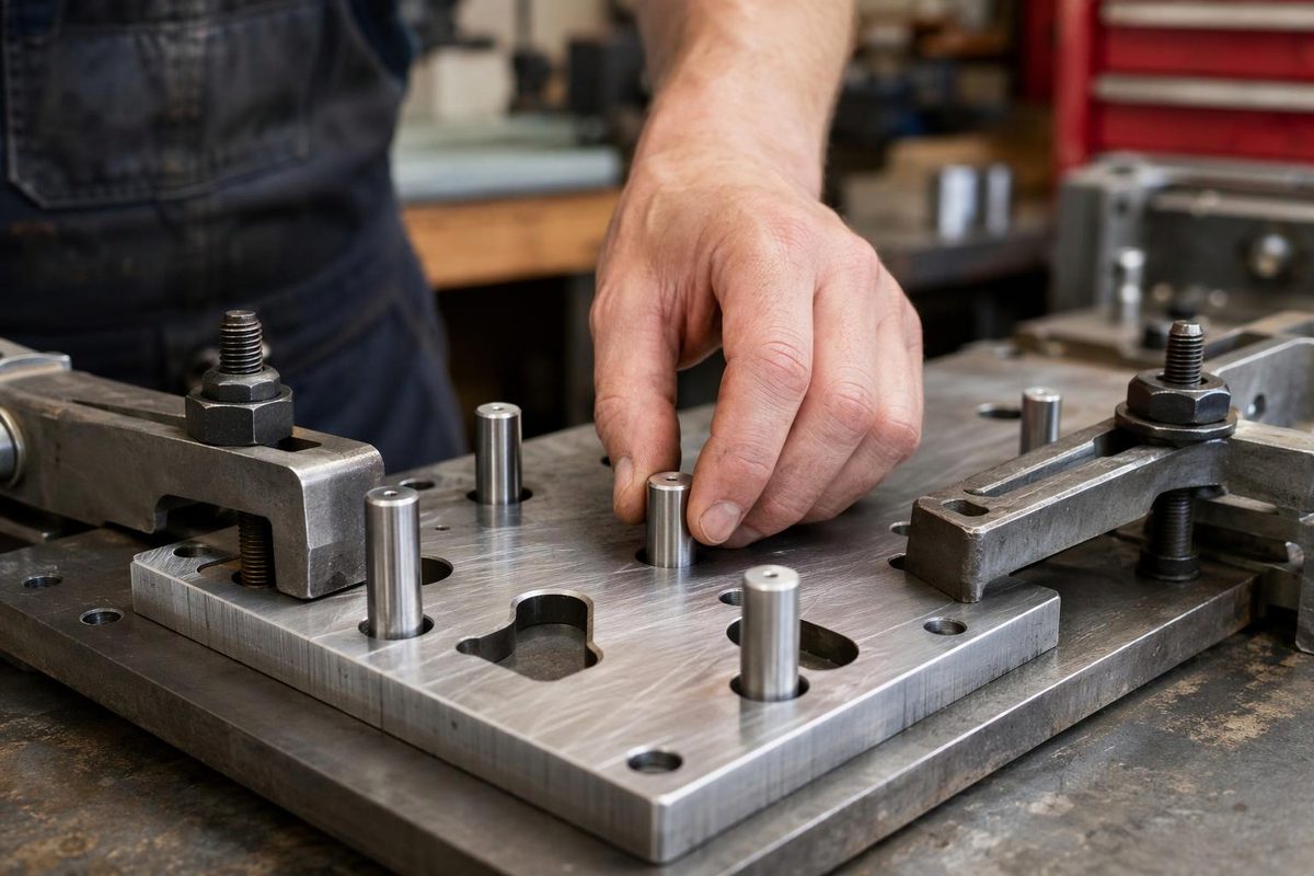
Clamp pins can provide a useful setup reference if their locating surfaces are fixed, their fit is suitable and the part returns to the same position after clamping. A screw that merely presses on the workpiece is not, by itself, a dependable reference. Separate what locates the part from what holds it there.
“Clamp pin” can mean different hardware. Carr Lane’s threaded clamping pins, for example, combine screw clamping with medium-accuracy alignment; depending on the extended screw length, they can also be used for clamping only. That description is not a precision-datum guarantee. Check the particular pin’s drawing and application details before relying on it. Carr Lane clamping pins
Choose the reference on the part first
Start with the feature from which the required dimensions are taken: a bottom face, a finished edge or an existing hole. Do not choose the reference merely because a convenient clamp happens to reach it.
Strictly, the datum is the reference plane, line or point; the datum feature is the real surface or hole on the part. The fixture contacts help establish that reference. This distinction matters when following a toleranced drawing: convenient pin locations do not override its datum requirements. KEYENCE datum guide
For a scratch-built jig without formal GD&T requirements, record the intended working references on your sketch. For example: “bottom face, long finished edge, left end.” Use those same references for layout and finished-part checks.
A straightforward edge-locating setup
For a rectangular plate whose holes are dimensioned from its edges, use:
- Three support points underneath, spread in a triangle, to establish the bottom reference.
- Two fixed pin contacts against the long edge, spaced well apart, to locate that edge and prevent the plate turning in its own plane.
- One fixed end stop to set the remaining lengthwise position.
- Clamps directed toward those contacts, with downward clamp loads over supports rather than unsupported spans.
This is the practical 3-2-1 locating arrangement. The fixed contacts establish position; opposing clamping forces keep the part seated. Additional supports for a flexible plate should be adjustable so they support the already-seated part rather than create a competing reference. Enerpac’s 3-2-1 explanation
Mount the pin contacts securely and leave them unchanged between parts. Clean and deburr the contacting edges, pin surfaces and supports. A chip trapped at one contact changes the seating. Carr Lane recommends widely spaced locators, chip relief and clamp forces directed into supports or locators to reduce positioning errors and deformation. Locating and clamping principles
Reference the pin’s contact surface, not automatically its centre. In plan view, a straight edge touching two equal-diameter cylindrical pins lies along their common external tangent. That tangent is one pin radius away from the line through their centres. If the jig sketch locates pin centres but your hole dimensions start at the plate edge, account for that offset. Verify the installed contact line rather than assuming nominal pin diameter and drilled mounting positions are exact.
If the pins locate through holes
A pin entering a hole references that hole, not the outside edge. Use this arrangement only when those holes are the intended locating features.
For a two-hole setup, a common solution is one round locating pin and one correctly oriented diamond—or relieved—pin. The round pin establishes position; the relieved pin controls rotation without redundantly constraining the hole spacing. Two close-fitting round pins can bind when the hole spacing differs from the fixture spacing. Carr Lane locating-pin guide
With combined locating-and-clamping pins, check which surface actually locates, how far it engages and what clearance remains. Tightening until movement disappears does not establish that the hole is centred on the pin.
Check the setup before making the cut
- Seat gently. The part should meet its intended contacts without rocking or binding. Do not use the clamp screw to bend or lever it into a fit.
- Watch while clamping. Put an indicator against a relevant accessible edge or face. Tighten in a consistent sequence and watch for movement at that point. Check other relevant locations if bowing is a concern.
- Reload several times. Release, remove, clean, reseat and reclamp. Record the observed positional range at the feature that matters—not only beside the locator.
- Compare with the job tolerance. Reload variation and clamp movement consume part of the available tolerance; measurement uncertainty and cutting error still remain.
A setup can repeat consistently in the wrong position. Verify its reference against the intended dimensions, then inspect the finished feature from those same references. If combined clamp pins cannot provide the needed location, use separate locating pins or stops and let the clamps do only the holding.