
How to Choose Linear Bearings for 20mm Shafts
Start with shaft support and bearing format, then verify tolerances, housing, loads, lubrication and alignment before ordering.
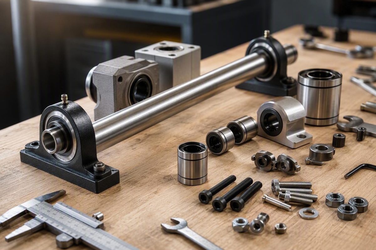
A search for linear bearings for 20mm shafts quickly produces parts labeled LM20UU, LME20UU, KH2030, SC20UU, EPS20, and many more. They may all mention 20 mm, but that does not make them mechanically interchangeable—or suitable for the same rail arrangement.
Use this selection sequence:
- Decide how the shaft will be supported.
- Choose an open, closed, housed, flanged, adjustable, self-aligning, or plain-bearing format.
- Verify the exact shaft and bearing tolerances.
- Size the complete arrangement for loads, moments, stroke, speed, environment, and life.
- Check housing, retention, lubrication, seals, and alignment.
- Approve the design from current manufacturer drawings and ratings, not a retailer title.
Nominal diameter narrows the search. It does not establish fit, load capacity, accuracy, or service life.
Editorial disclosure: Last reviewed September 3, 2026. This guide compares the supplied manufacturer guidance and retailer listings as a desk-based preliminary selection exercise. It does not claim hands-on testing of the featured bearings. Product dimensions, ratings, prices, and availability should be rechecked against current manufacturer documents before purchase.
Start With the Rail: Supported or Unobstructed?
Before comparing bearing models, draw the shaft and its supports. A nominal 20 mm shaft may be:
- End-supported, leaving most of its length unobstructed.
- Unobstructed but supported at intermediate points outside the bearing’s travel.
- Continuously supported along its underside.
- Part of a preassembled shaft-and-bearing guide.
That choice determines whether the bearing can physically travel along the rail.
Closed bearings need a clear path
A closed round bushing encircles the shaft. Its body therefore generally needs an unobstructed shaft over the full stroke. This is the familiar arrangement in which a cylindrical bushing travels over a round bar held by end supports.
End-supported shafts can be useful where the guide must span a gap or where no continuous mounting surface exists. The disadvantage is bending: the shaft behaves as a beam between its supports. Increasing the load or span, or moving the load toward a less favorable position, can increase deflection.
Do not choose an unsupported span from a rule based only on shaft diameter. Calculate deflection from the actual span, shaft section, load magnitude and position, support conditions, and permissible displacement. Manufacturer guidance treats shaft support as a system-level decision because deflection can affect alignment, accuracy, load sharing, and bearing life.
Open bearings clear a support beneath the shaft
A continuously supported shaft normally sits on a support rail along its underside. A closed bushing cannot pass over that rail. An open bearing has a relieved section through its body so the support can pass beneath it.
The initial decision path is therefore:
- Unobstructed shaft: investigate a closed bearing.
- Continuously supported shaft: investigate an open bearing.
- Uncertain end-support stiffness: calculate shaft deflection before choosing the arrangement.
Long or heavily loaded shafts may benefit from continuous support, but there is no universal maximum unsupported span for every 20 mm shaft.
As format examples, PBC Linear lists EPS20 as a closed self-aligning 20 mm ball bearing and EPS20-OP as its open counterpart. VXB lists SME20LUU as an open housed unit and also mixes bare bearings, blocks, shafting, and complete motion systems in the same 20 mm collection. These listings identify possible formats; they do not provide enough engineering data to approve a machine design. See the VXB 20 mm collection and its mixed product categories.
A complete system can reduce—but not eliminate—matching risk
It does not establish whether the system can carry the actual forces and moments, survive the required duty cycle, tolerate the environment, or meet the required accuracy. A complete assembly still needs application-specific verification.
Decode the Main 20 mm Bearing Formats
“20 mm linear bearing” describes a nominal shaft size, not a complete construction. The product may be a bare bushing, a block containing a bushing, a flange-mounted unit, or one component in a complete guide.
| Representative model | Construction | Open or closed | Supplied housing | Mounting method | Known dimensions or features | Seals or liner | Major engineering data still missing |
|---|---|---|---|---|---|---|---|
| EPS20 | Self-aligning recirculating-ball bearing | Closed | No housing confirmed | Requires manufacturer-specified housing and retention | 20 mm nominal ID | Not established | Full drawing, tolerances, ratings, speed, lubrication, temperature |
| EPS20-OP | Self-aligning recirculating-ball bearing | Open | No housing confirmed | Requires a compatible open housing over a supported shaft | 20 mm nominal ID | Not established | Support geometry, dimensions, ratings, limits |
| FMT20 | Thin-wall plain bearing with sliding liner | Not confirmed | No housing confirmed | Installation method must be verified | 20 mm nominal ID | Self-lubricating FrelonGOLD liner | Housing requirements, loads, speed, shaft requirements, temperature |
| JPF20G | Round-flanged recirculating-ball bearing | Closed | Flanged body listed | Flange mounting; exact interface requires drawing | 20 mm nominal ID; standard-width body listed | Double sealed | Flange dimensions, hole pattern, ratings, fit |
| KH2030 | Compact ball bushing | Closed | No | Compatible housing and retention required | 20 × 28 × 30 mm | Listed without PP seal designation | Tolerances, ratings, speed, lubrication |
| KH2030PP | Compact ball bushing | Closed | No | Compatible housing and retention required | 20 × 28 × 30 mm | Listed as sealed | Seal capability, tolerances, ratings, limits |
| LME20UU-style | Ball bushing | Closed | No | Compatible housing and retention required | 20 × 32 × 45 mm | Listed as sealed | Manufacturer identity, ratings, tolerances |
| SC20UU | LM20UU-type bearing in a block | Closed | Yes | Four mounting holes | 20 mm shaft designation | Not established | Hole spacing, thread size, ratings, accuracy, lubrication |
| SME20LUU | Open ball-bearing block | Open | Yes | Block fasteners over a supported shaft | 20 mm shaft designation | Not established | Mounting pattern, ratings, tolerances, support compatibility |
| SMA20VUU | Short pillow-block bearing | Not confirmed | Yes | Pillow-block mounting | 20 mm shaft designation | Not established | Detailed dimensions, ratings, seals, mounting pattern |
The EPS20, EPS20-OP, FMT20, and JPF20G classifications and features come from the PBC Linear product listing. The KH, LME, and SME dimensions and formats come from the VXB collection cited above. Motedis identifies SC20UU as a four-hole block containing an LM20UU-type bearing, while the SMA20VUU retailer page confirms only a short pillow-block format for a 20 mm shaft.
Bare bushings
A bare bushing supplies the bearing mechanism but not necessarily the structure needed to attach it to a carriage. The builder may need to provide:
- A housing bore with the specified size, tolerance, geometry, and surface condition.
- Axial retention, such as shoulders, rings, plates, or another approved method.
- Enough housing stiffness to avoid distorting the bearing.
- Installation and lubrication access.
- Rotational retention where required.
KH2030 and KH2030PP are listed as 20 × 28 × 30 mm bushings, with the PP version identified as sealed. The listed LME20UU-style products measure 20 × 32 × 45 mm. Those different outside diameters and lengths are enough to show that the series names cannot be treated as synonyms.
Housed pillow blocks
A pillow block places the bushing in a mountable housing. This can avoid machining a precision bearing bore, but the block’s height, footprint, hole spacing, thread size, fastener access, and reference surfaces become part of the design.
SC20UU is listed as a four-hole housed block containing an LM20UU-type bearing. The available listing does not provide enough dimensions or ratings to design the surrounding carriage confidently; “four holes” is not a mounting drawing. Motedis provides the SC20UU construction and limited mounting description.
SMA20VUU is another listed short pillow block for a 20 mm shaft. Because the supplied evidence lacks its detailed dimensions, ratings, seal information, and mounting geometry, it remains a candidate to investigate rather than a selectable component.
Flanged units
A flanged bearing places the mounting interface around one end or section of the body. This can suit plate-mounted assemblies where a separate cylindrical housing would be awkward.
“Flanged” does not define the flange shape, bolt circle, pilot diameter, body length, or allowable load. JPF20G is listed as a round-flanged, double-sealed ball bearing, but its bolt pattern and fit still require a current drawing.
Adjustable and self-aligning bearings
An adjustable bearing is intended to permit fit adjustment after installation. That does not establish a particular clearance range or preload capability. Those values—and the required housing construction—must come from the selected model’s documentation.
A self-aligning bearing is designed to accommodate some alignment error within its specified construction. It does not make rail geometry irrelevant or authorize the builder to ignore parallelism, housing distortion, or shaft deflection.
Recirculating-ball versus plain bearings
A recirculating-ball bushing carries load through rolling elements circulating through tracks. A plain bearing slides on a lined surface without recirculating balls.
That structural difference is the safe general comparison. Friction, noise, maintenance, speed, wear, load, and life depend on the exact bearing, shaft, lubrication, environment, and operating conditions. “Plain” does not automatically mean maintenance-free, and “ball bearing” does not automatically mean higher capacity.
Why a 20 mm Label Does Not Prove Fit
Four distinct dimensions or conditions are often collapsed into the phrase “20 mm”:
- Nominal shaft diameter: the family designation.
- Actual shaft diameter and tolerance: what the shaft may physically measure.
- Bearing bore or effective running geometry: the bearing’s permitted shaft range.
- Operating clearance or preload: the relationship after installation in the housing.
A nominally 20 mm bearing can be too tight, too loose, or otherwise unsuitable for a nominally 20 mm shaft if those details do not agree.
A manufacturer-specific shaft example
Thomson’s obsolete 20 MM Class MM (h6) shaft illustrates the difference between nominal size and a complete specification. It is listed with:
- Nominal diameter: 20 mm
- Actual diameter: 19.99–20.00 mm
- Minimum hardness: 60 HRC
- Minimum case depth: 1.52 mm
- Surface finish: 0.20 Ra µm
- Roundness: 0.0020 mm
- Straightness: 0.0254 mm per foot cumulative
- Stated straightness TIR: 0.051 mm
These values belong to that specific, obsolete shaft. They do not prove that h6 shafting is required for EPS20, LM20UU, LME20UU, KH2030, or every other nominally 20 mm bearing. Thomson’s product page provides the listed dimensions and surface specifications.
Why shaft condition matters
In a ball bushing, small contact areas carry the ball loads. Shaft hardness and case depth affect resistance to permanent deformation and wear. Surface finish affects rolling contact and lubricant behavior. Roundness and straightness affect track loading and whether the assembly travels without localized tight spots.
Material matters as well. A corrosion-resistant but softer shaft is not automatically equivalent to hardened carbon-steel shafting. Softer or non-hardened shafting may require another bearing technology or a manufacturer-approved derating. Do not transfer one vendor’s material guidance to an unrelated product without confirmation.
Before ordering, compare the bearing and shaft documents for:
- Actual diameter and tolerance
- Permitted shaft tolerance class
- Shaft material and coating
- Surface and core hardness, where specified
- Case depth
- Surface finish
- Roundness and straightness
- Bearing clearance or intended preload
- Housing effects on clearance
- Lubricant and material compatibility
Manufacturer-authored round-shaft guidance connects hardness, straightness, finish, roundness, material, support, and mounting configuration to operation and life. It also discusses short-stroke and soft-shaft corrections, which must be taken from the selected manufacturer rather than copied across brands. Thomson’s shaft-selection guide explains these interdependent factors.
Pre-purchase fit record
- [ ] Exact bearing manufacturer and model:
- [ ] Bearing drawing or catalog revision:
- [ ] Exact shaft manufacturer and model:
- [ ] Nominal shaft diameter:
- [ ] Actual shaft tolerance:
- [ ] Required bearing clearance or preload:
- [ ] Shaft hardness, case depth, finish, roundness, and straightness:
- [ ] Bare-bearing housing bore and tolerance, or housed-block dimensions:
- [ ] Bearing and shaft material or coating compatibility:
- [ ] Axial and rotational retention method:
- [ ] Closed bearing on an unobstructed shaft, or open bearing on a supported rail:
- [ ] Written confirmation for any proposed cross-brand interchange:
Do not assume LM20UU, LME20UU, KH2030, SC20UU, SMA20VUU, EPS20, or similarly labeled series are interchangeable. Compare every functional dimension and tolerance on current drawings.
Size the System, Not Just the Bushing
A bearing supports a carriage under combined forces created by mass, acceleration, gravity, tooling, belts or screws, and off-center work. Selecting by bore diameter alone ignores most of the application.
Complete this worksheet before asking a supplier for a model:
| Application input | Record |
|---|---|
| Moving carriage mass | |
| Payload and maximum payload position | |
| External process forces | |
| Force directions and reversals | |
| Pitch moment | |
| Roll moment | |
| Yaw moment | |
| Shock or impact | |
| Desired service life | |
| Stroke length | |
| Maximum and typical speed | |
| Acceleration and deceleration | |
| Cycles per hour or day | |
| Duty cycle | |
| Mounting orientation | |
| Operating temperature | |
| Dust, chips, coolant, water, or chemicals | |
| Corrosion or material constraints | |
| Shaft span and support arrangement | |
| Allowable shaft and carriage deflection | |
| Required positioning or repeatability | |
| Number of rails | |
| Number of bearings | |
| Rail center distance | |
| Bearing spacing along each rail | |
| Calculated reaction at each bearing |
Evaluate the load at each bearing
Loads are rarely divided equally. An off-center payload can increase the reaction at one bearing or one end of the carriage. Each bearing’s dynamic equivalent load must be evaluated, and the most heavily loaded bearing may control selection.
For final sizing, obtain the selected manufacturer’s:
- Static and dynamic load ratings
- Load-direction factors
- Permitted moments
- Static safety method
- Dynamic life method
- Shock or application factors
- Speed and acceleration limits
- Temperature limits
- Preload or clearance options
- Lubrication assumptions
The supplied retailer listings omit enough comparable engineering data that they cannot support a capacity calculation or final model recommendation. Manufacturer guidance calls for sizing from the dynamic equivalent load at each bearing and checking the most heavily loaded position. Design World’s manufacturer-authored guide summarizes these sizing requirements.
Why round-shaft carriages commonly use two rails
One cylindrical bushing on one round shaft does not provide a stable answer to every pitch, roll, and yaw moment. Round-shaft systems therefore commonly use two parallel rails with multiple bearings.
More rails are not automatically better. Three or more parallel rails can create a statically indeterminate or over-constrained arrangement in which small height, straightness, or parallelism errors prevent natural load sharing. Manufacturer guidance recommends treating mounting accuracy and load distribution as system-level issues rather than simply adding guides. NB Corporation discusses paired round rails and the risks of multi-rail arrangements.
Short strokes need special attention
In a short stroke, rolling elements repeatedly load the same limited shaft region. Manufacturer guidance indicates that strokes below roughly 1.5–2 bearing lengths may require product-specific load-capacity or life corrections. Use the selected manufacturer’s method rather than applying a generic correction.
Know when to stop selecting from listings
Obtain manufacturer or qualified engineering review if guide failure could cause injury, uncontrolled machine motion, a dropped load, loss of guarding, or another hazardous event. Do the same when critical accuracy depends on load sharing, thermal behavior, or structural deflection that has not been analyzed.
This is a conservative design stop condition, not a claim that any listed product is unsafe. A retailer description can identify candidates, but it cannot establish a safety margin.
Check Housing, Seals, Lubrication, and Environment
A suitable bearing can still perform poorly in an unsuitable installation.
Housing and retention
A bare bushing requires a correctly specified housing bore. The bore must hold the bearing without creating unintended distortion or clearance. The assembly also needs axial retention and, where applicable, control against rotation.
A housed block reduces this work but introduces other checks:
- Overall height and rail centerline
- Footprint and mounting-hole spacing
- Hole or thread size
- Fastener grade and engagement
- Datum surfaces
- Housing stiffness
- Tightening and lubrication access
- Compatibility with the carriage plate
SC20UU is a confirmed four-hole block containing an LM20UU-type bearing, but its available retailer data does not establish mounting-hole spacing, thread details, or block performance. JPF20G includes a round flange, but its bolt pattern still requires a drawing.
For general fastening practice, see Bolt Torque Basics for Builders: Specs, Sequence & Feel; product-specific instructions override general guidance.
Seals are not an environmental rating
“Sealed” or “double sealed” identifies a configuration. It does not prove protection against:
- Metal or wood chips
- Abrasive grinding dust
- Coolant
- Water spray
- Fine powder
- Outdoor corrosion
- Aggressive cleaners or chemicals
Confirm the selected seal or wiper design, exposed materials, coating compatibility, and permitted environment.
Lubrication requires product-specific instructions
Before assembly, determine:
- Whether the bearing is supplied lubricated
- Required lubricant type and viscosity
- Initial lubrication procedure
- Relubrication quantity and interval
- Whether the shaft needs a lubricant film
- Compatibility with seals, liners, coatings, and process chemicals
- Permitted temperature range
FMT20 is listed with a self-lubricating FrelonGOLD liner. That wording should not be expanded into a universal promise of maintenance-free operation under every load, speed, shaft material, temperature, or contamination level.
Technical guidance identifies insufficient lubrication, contamination, misalignment, shock, excessive static load, and incorrect bearing-to-shaft fit as possible failure causes.
Count the complete hardware
The installed guide may require:
- Bearings or housed blocks
- Shafting
- End supports or continuous shaft supports
- Bearing housings
- Retaining rings, shoulders, caps, or clamps
- Flange or block fasteners
- Seals, wipers, or protective covers
- Lubricant and access fittings
- Carriage plate
- Shims, adjustment slots, dowels, or other alignment provisions
- Drive attachment hardware
This bill of materials—not the bushing alone—determines installation work and total cost.
Align a Dual-Shaft Assembly Without Binding
The following sequence is based on PBC Linear’s procedure for Simplicity self-lubricating bearings. It is a useful installation pattern, not a universal numerical alignment specification for every ball bushing or block.
- Choose the master rail. If the load is off-center, use the rail nearest the load. If the load is centered, either rail may be the master.
- Fully secure the master rail. Establish it as the primary reference.
- Install its bearing assemblies. Confirm that each slides freely before connecting the carriage.
- Place the follower rail without final tightening. Leave enough freedom for it to settle into alignment.
- Install the follower-side bearings. Check that they move freely on that rail independently.
- Connect both sides with the carriage plate or bracket. Do not use the plate to force grossly misaligned parts into position.
- Move the carriage through the full stroke. Check for tight spots before tightening the follower rail.
- Tighten follower fasteners incrementally. Start at one end, then move the carriage through the complete stroke again.
- Repeat progressively. Continue tightening and testing, adjusting the follower rail as needed.
- Complete final tightening only after free travel is maintained.
The master-and-follower sequence, including full-stroke checks during progressive tightening, comes from PBC Linear’s dual-shaft alignment procedure.
The procedure does not provide a universal numerical parallelism tolerance. Obtain that value from the selected bearing or guide manufacturer and the machine’s accuracy requirements.
Practical checks when the carriage drags
Before forcing anything:
- Disconnect or isolate the screw, belt, motor, gearbox, or coupling where practical.
- Move the carriage by hand to separate bearing drag from drive-system drag.
- Test each rail and bearing assembly independently.
- Check whether drag appears only after the carriage plate is tightened.
- Look for bent shafts, damaged surfaces, raised burrs, and contamination.
- Measure shaft deflection under carriage load.
- Check whether the housing or carriage plate distorts during tightening.
- Confirm that the bearing is not being forced over a support or retention feature.
Do not repeatedly power a binding carriage through its stroke. The cited manufacturer procedure warns that misalignment can increase friction, accelerate wear, and cause binding; stopping and isolating the drive is a conservative precaution when unexpected resistance appears.
Representative Products and a Qualified Price Snapshot
The values below are undated observations from the supplied listings. No defensible capture date was provided, so they must not be read as prices current on the editorial review date. The table is not a ranking, recommendation, performance comparison, or delivered-price quotation.
| Seller | Model | Format | Known dimensions or features | Undated displayed price | Unit count | Housing included? | VAT note | Major missing specifications |
|---|---|---|---|---|---|---|---|---|
| PBC Linear | EPS20 | Closed self-aligning ball bearing | 20 mm ID | $31.45 | 1 | No housing confirmed | Not stated | Dimensions, ratings, tolerances, speed, lubrication |
| PBC Linear | EPS20-OP | Open self-aligning ball bearing | 20 mm ID | $31.60 | 1 | No housing confirmed | Not stated | Support geometry, ratings, drawing, limits |
| PBC Linear | FMT20 | Thin-wall plain bearing | 20 mm ID; FrelonGOLD liner | $18.91 | 1 | No housing confirmed | Not stated | Installation method, housing fit, loads, speed, shaft requirements |
| PBC Linear | JPF20G | Round-flanged ball bearing | 20 mm ID; double sealed | $31.48 | 1 | Flanged body listed | Not stated | Flange dimensions, ratings, fit, environment |
| VXB | KH2030 | Ball bushing | 20 × 28 × 30 mm | $9.99 | 1 | No | Not stated | Ratings, tolerance, lubrication |
| VXB | KH2030PP | Sealed ball bushing | 20 × 28 × 30 mm | $14.99 | 1 | No | Not stated | Seal capability, ratings, tolerance |
| VXB | LME20UU | Sealed ball bushings | 20 × 32 × 45 mm each | $29.99 pack price | 4 | No | Not stated | Manufacturer identity, ratings, tolerance |
| VXB | SME20LUU | Open housed unit | For a supported 20 mm rail | $19.99 | 1 | Yes | Not stated | Block drawing, ratings, mounting details |
| Motedis | SC20UU | Four-hole block with LM20UU-type bearing | For a 20 mm shaft | $7.81 | 1-piece pack | Yes | Excludes VAT | Block dimensions, threads, ratings, seals |
| Motedis | SC20UU | Same housed block | For a 20 mm shaft | $7.10 each | 4-piece pack | Yes | Excludes VAT | Same omissions |
| Bearings Direct | SMA20VUU | Short pillow-block bearing | For a 20 mm shaft | Not supplied | Not supplied | Yes | Not stated | Price, dimensions, ratings, seals, mounting pattern |
The PBC values and configurations come from its product listing cited earlier. The VXB values come from its cited 20 mm collection. Motedis supplies the SC20UU pack pricing and VAT qualification on its cited product page. Bearings Direct confirms the SMA20VUU format and 20 mm designation but supplies no captured price or detailed dimensions.
Why the lowest displayed price may not be the lowest-cost system
A fair comparison must normalize:
- Single unit versus multipack
- Bare bearing versus housed block
- Open bearing plus supported rail versus closed bearing plus end supports
- Included seals and retention
- VAT
- Shipping and processing
- Required machining
- Carriage and support hardware
- Alignment labor
- Availability of drawings and engineering support
A more expensive block may avoid machining a housing. A cheaper bare bushing may be appropriate if the machine already has the correct bore. A complete guide may reduce component-matching work. None of those outcomes can be inferred from list price alone.
Immediately before ordering, verify the current price, quantity, availability, processing time, shipping, tax treatment, and full manufacturer datasheet.
When a Profile Rail May Be the Better Starting Point
A profile rail is not another bearing for a 20 mm round shaft. It is a different guide architecture, using a shaped rail and matching carriage.
Reasons to favor a round-shaft system
A round-shaft system may deserve priority when:
- The guide must span a gap.
- A continuous precision-machined mounting surface is unavailable.
- Some tolerance of mounting or alignment imperfections is useful.
- End or localized support suits the machine structure.
- The design benefits from separately replaceable shafts, supports, and bearings.
- Initial component and machining costs dominate the decision.
Manufacturer guidance describes round-rail systems as generally more tolerant of mounting-surface and alignment imperfections than profile rails, depending on bearing construction. Whether they are easier or cheaper in a particular scratch-built machine still depends on the available tools, structure, and required accuracy.
Reasons to investigate a profile rail
Profile rails generally offer greater stiffness, accuracy, load capacity, and multidirectional moment resistance. A single profile rail and carriage arrangement can resist moments that commonly lead designers to use paired round shafts.
Those advantages come with stricter installation demands. Profile rails normally need a straight, flat, continuously supported mounting surface and more precise alignment.
Vendor-authored guides quote substantial stiffness differences between broad product classes, but those figures depend on geometry, size, preload, mounting, and load direction. They should not be applied to the named 20 mm products in this guide.
Practical decision summary
Favor a round-shaft system when mounting tolerance, gap spanning, modular construction, or initial cost dominates.
Investigate a profile rail when rigidity, compact multidirectional moment support, positioning accuracy, or a small carriage envelope dominates.
Compare total installed cost in either case:
- Base and rail machining
- Shaft or rail supports
- Bearing blocks or carriages
- Alignment labor
- Carriage plate complexity
- Fasteners and locating features
- Lubrication and protection
- Replacement availability
- Compatibility risk
Final Pre-Purchase and Troubleshooting Checklist
Print or copy this checklist into the project file.
Before ordering
- [ ] Shaft arrangement selected: unobstructed, end-supported, or continuously supported
- [ ] Open or closed bearing chosen to match the support arrangement
- [ ] Bearing format selected: bare, housed, flanged, adjustable, self-aligning, or plain
- [ ] Exact manufacturer and model recorded
- [ ] Current drawing and revision obtained
- [ ] Exact shaft manufacturer and model recorded
- [ ] Actual shaft diameter and tolerance verified
- [ ] Bearing bore tolerance or permitted shaft range verified
- [ ] Intended operating clearance or preload confirmed
- [ ] Shaft material and coating confirmed
- [ ] Shaft hardness and case depth confirmed where required
- [ ] Shaft finish, roundness, and straightness confirmed
- [ ] Bare-bearing housing bore and tolerance confirmed
- [ ] Housed-block height, footprint, hole spacing, and threads confirmed
- [ ] Axial and rotational retention defined
- [ ] Static and dynamic load ratings obtained
- [ ] Load-direction and shock factors obtained
- [ ] Pitch, roll, and yaw moments calculated
- [ ] Number of rails and bearings recorded
- [ ] Rail and bearing spacing recorded
- [ ] Reaction at each bearing calculated
- [ ] Stroke checked, including any short-stroke correction
- [ ] Maximum speed and acceleration checked
- [ ] Duty cycle and desired life documented
- [ ] Temperature limits checked
- [ ] Seals or wipers matched to the contamination
- [ ] Initial lubricant and relubrication plan documented
- [ ] Shaft support span checked by deflection calculation
- [ ] Parallelism and mounting-surface requirements obtained
- [ ] Carriage and base stiffness considered
- [ ] Fastener access and tightening sequence planned
- [ ] Total bearing quantity confirmed
- [ ] Supports, retainers, fasteners, lubricant, and covers included in the bill of materials
- [ ] Current price, tax, shipping, and availability confirmed
- [ ] Any claimed interchangeability confirmed in writing
If the carriage binds or develops high drag
Possible causes include:
- Rail misalignment
- Incorrect bearing-to-shaft fit
- Excessive preload
- Shaft deflection
- Bent or damaged shafting
- Contamination
- Housing distortion
- A twisted or insufficiently stiff carriage plate
- Drive-system drag rather than guide drag
Where practical, disconnect or isolate the screw, belt, motor, or coupling. Test each bearing and rail independently, then test the connected carriage before reintroducing the drive.
If wear is uneven
Inspect for:
- Poor load sharing
- Off-center loads or underestimated moments
- Rail-height or parallelism error
- Different bearing clearances
- Shaft damage or inconsistent surface condition
- Contamination entering one side
- Uneven lubrication
- Local shaft deflection
Uneven wear indicates where to investigate; it does not identify a single cause without inspection and measurement.
If play or repeatability gets worse
Check:
- Bearing clearance
- Loose block, flange, support, or carriage fasteners
- Shaft deflection
- Housing movement
- Shaft or bearing wear
- Retention movement
- Structural flexibility
- Drive backlash or coupling looseness
Do not assume the bearing is responsible until guide motion has been separated from drive motion.
Frequently Asked Questions
Will an LM20UU bearing fit every 20 mm shaft?
No. “20 mm” is nominal. The shaft’s actual diameter and tolerance, hardness, finish, roundness, straightness, and material must agree with the bearing requirements. The housing can also affect clearance.
An LM20UU designation should not be assumed compatible with every nominally 20 mm shaft or interchangeable with LME20UU, KH2030, EPS20, or another series. Compare current manufacturer drawings and obtain written confirmation where compatibility is unclear.
What is the difference between open and closed linear bearings for a 20 mm shaft?
A closed bearing encircles the shaft and generally needs an unobstructed travel path. It is commonly considered for an end-supported shaft.
An open bearing has a relieved section that clears the support under a continuously supported shaft. This arrangement can help control deflection on long or heavily loaded axes. The choice depends on the actual span, load, support geometry, and permissible deflection—not shaft diameter alone.
Are KH2030 and LME20UU bearings interchangeable?
Not on the available evidence. The supplied listings show different outside diameters and lengths, so they cannot occupy the same unmodified housing.
Even identical envelope dimensions would not prove interchangeability. Tolerances, seals, internal geometry, load ratings, clearance, and retention details would still need comparison.
How many linear bearings and shafts should a round-rail carriage use?
There is no universal quantity. Two parallel shafts with multiple bearings are common because rail and bearing spacing help resist pitch, roll, and yaw moments. The required number and spacing depend on carriage loads, moments, stiffness, stroke, and verified manufacturer ratings.
Adding more rails can make alignment harder rather than increasing usable capacity. Three or more parallel rails may over-constrain the assembly when mounting geometry is imperfect. Calculate the reaction at each bearing and size the system for the most heavily loaded position.
How do I align two 20 mm shafts so the carriage does not bind?
Establish and fully secure one master rail, preferably the rail nearest an off-center load. Check that its bearings slide freely. Position the follower rail without final tightening, install its bearings, and connect both sides with the carriage plate.
Move the carriage through its full stroke, then tighten the follower-rail fasteners progressively while repeatedly checking free motion. Complete final tightening only after the carriage remains free over the entire stroke. If it binds, isolate the guide from the drive and inspect rail alignment, shaft condition, deflection, bearing fit, and housing distortion rather than forcing the carriage.
The final rule is simple: retailer collections help discover candidates, but current manufacturer drawings, tolerance data, ratings, and installation instructions govern selection. Do not buy from bore diameter alone. Decide on shaft support first, choose the appropriate bearing format, and verify the exact shaft, bearing, housing, load, environment, and alignment as one mechanical system.