
Roll Pin: Identify the Type, Size the Hole and Install It
Identify slotted and coiled roll pins, choose the specified hole size, and install or remove them with the right support and punch.
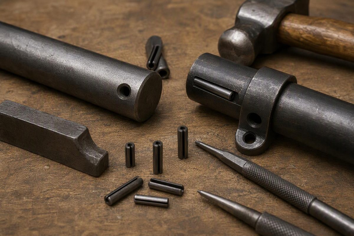
A roll pin is a spring pin that compresses during installation and holds itself in the hole by outward pressure. Its loose outside diameter is intentionally larger than the receiving hole. Do not drill a hole to match that loose measurement: identify the pin and use its specified hole range.
“Roll pin” can mean either a slotted spring pin or a coiled spring pin. The difference matters when choosing a replacement—and when choosing a punch. SPIROL’s roll-pin guide describes both types and their retention mechanism.
Identify the pin before ordering
Look at an undamaged end, not just the side.
| Type | What you should see | What to specify |
|---|---|---|
| Slotted spring pin | A hollow, C-shaped section with one longitudinal slot | Nominal diameter, length, material, finish and applicable specification |
| Coiled spring pin | A spiral section with multiple wraps | Nominal diameter, length, duty, material, finish and applicable specification |
Coiled pins are available in light, standard and heavy duty. Those duties balance strength and flexibility; heavy duty is not automatically a better replacement. SPIROL recommends evaluating the host material, loads, environment and installation method before selecting a pin. Its selection guidance favors coiled pins for dynamic applications and ground solid dowels for highly critical alignment. See the manufacturer’s pin-selection guidance.
For a repair, record the original pin’s type, length and any available part number before removal. Measure its outside diameter as an identification clue, not as the finished-hole target. A distorted used pin may not represent its original dimensions. Keep those observations with your replacement-part identification records.
For steering, braking, lifting or another joint whose failure could injure someone, use the specified replacement or obtain an engineered selection. Matching diameter and length alone does not establish suitability.
Choose the hole from the pin specification
A concrete example shows why the loose diameter can mislead. For SPIROL part 192501500, a standard inch slotted pin in high-carbon steel, the published dimensions are:
| Feature | Published dimension |
|---|---|
| Nominal diameter | 0.250 in. (1/4 in.) |
| Length | 1.500 in. |
| Uninstalled outside diameter | 0.258–0.264 in. |
| Recommended hole diameter | 0.250–0.256 in. |
These values belong to that specific SPIROL part, not every pin sold as a 1/4-inch roll pin. A hole matched to its uninstalled diameter would be outside the recommended range.
For a new part:
- Select the pin first. Put the supplier’s hole limits on the drawing.
- Hold the mating parts in their intended alignment. Pin flexibility is not permission to leave their holes offset.
- Drill and lightly deburr the entrances. Remove raised edges without creating a large countersink that sacrifices engagement.
- Verify the finished hole. The drill marking states nominal tool size, not the diameter, straightness or taper actually produced. Use suitable pin gauges or bore-measuring equipment for the specified tolerance.
Choose length as carefully as diameter. The chamfered ends must not lie at the joint interface where the pin carries shear. SPIROL’s retention guidance explains that a chamfer at this interface can turn transverse loading into axial force and encourage the pin to walk out.
Install with support and axial control
Have the correct pin, a suitable driver, a hammer or press, and a rigid support with clearance beneath the hole. Both the user and bystanders should wear safety goggles, as Wright Tool warns for its pilot punches.
Support the component close to the hole so installation force does not bend a thin bracket or pass unnecessarily through a bearing. Confirm hole alignment, place the pin’s chamfered end squarely at the entrance, then advance it along the hole axis to the specified depth.
For a slotted pin, a correctly sized roll-pin pilot punch helps locate the driver in the hollow end. Wright Tool describes this rounded-tip tool as intended for installing and removing roll pins.
For a coiled pin, use tooling intended for coiled pins rather than assuming the slotted-pin punch is suitable. SPIROL describes hammer installation for a few prototypes and a press with a pin-driving chuck for better alignment and depth control. The chuck’s internal punch must be smaller than the hole but larger than the pin’s chamfer diameter. A chuck also holds small pins that are difficult to hold by hand. See its installation instructions.
Stop if the pin tilts, its end deforms, or progress stops abruptly. Check alignment, burrs, hole size and available depth before adding force. After installation, inspect seating depth, the surrounding material and the assembly’s intended movement.
Remove it without damaging the hole
For a through-hole, support the part and leave an unobstructed exit path. Use the appropriate punch and drive the pin out along its axis.
For coiled pins, SPIROL specifies a flat, square-ended, constant-diameter punch of the same nominal diameter as the hole. It warns against round ball-end punches, which are effective for slotted pins but unsuitable for coiled-pin removal. The contacting tip must not be smaller than the diameter of the pin’s outermost coil. See its removal instructions.
A blind hole has no drive-through exit. Do not keep hammering a bottomed pin or assume drilling it out will preserve the bore. SPIROL identifies blind-hole removal of coiled pins as substantially harder, with EDM or carefully controlled drilling among the options. For a scratch-built assembly that will need servicing, provide a through-hole and room for a removal punch before making the part.