
Mag Drill Bits: Match the Shank, Pilot and Cutting Depth
Choose annular cutters for a magnetic drill by shank, hole diameter, cutting depth and pilot pin, then check magnet support and finished fit.
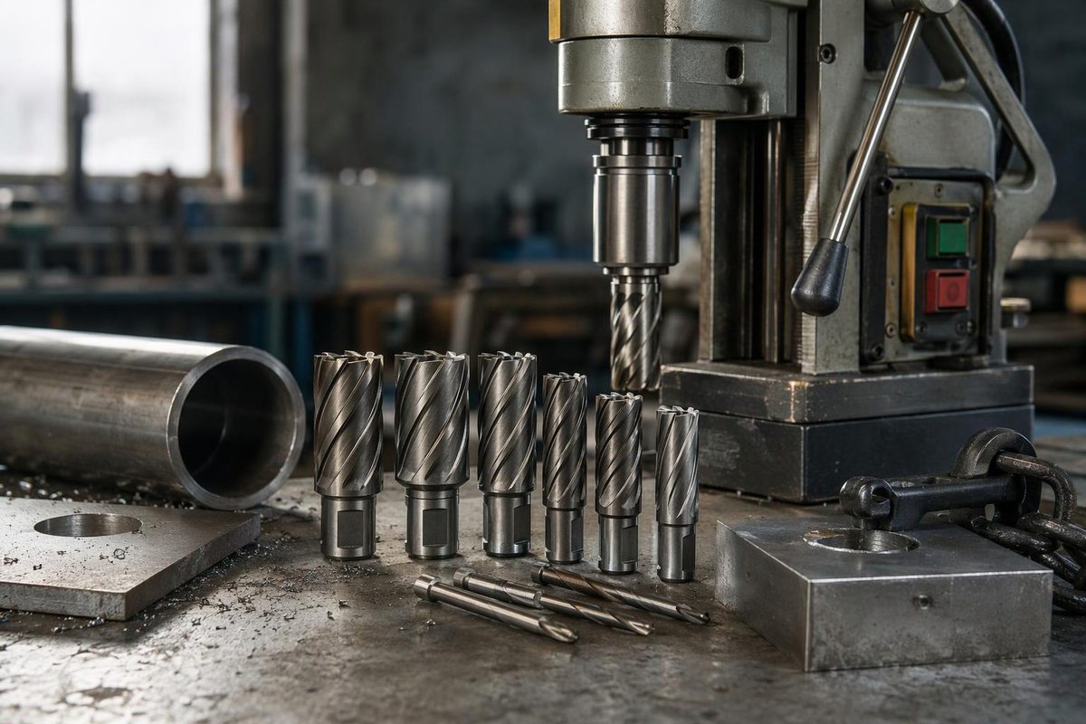
For a through-hole in a steel frame plate or fabricated bracket, the “mag drill bit” you usually want is an annular cutter. It cuts a ring around the hole and leaves a solid center slug, rather than turning the whole hole into chips. A normal annular-cutting operation does not require a predrilled pilot hole. Euroboor’s operating manual explains that distinction.
Before ordering, record the drill model and arbor type, required finished-hole diameter, material and thickness. Then match the cutter and pilot as a pair—not just the diameter printed on the box.
Check the mount before the cutting size
A common annular-cutter mount is a 3/4-inch (19.05 mm) Weldon-style shank, retained by screws against flats. But “for magnetic drills” is not a universal fit specification. Larger arbors and proprietary quick-change systems also exist.
For example, Hougen’s HMD904 accepts 3/4-inch-shank cutters, while its HMD130 uses a bayonet-style RotaLoc Plus mount. Those are different connections even though both machines are mag drills. Hougen’s catalog lists the mounts by model.
| Check | What must match |
|---|---|
| Shank | Diameter and retention geometry: flats, detents or bayonet connection |
| Hole diameter | The drawing’s clearance or machining requirement, not simply the bolt’s nominal diameter |
| Depth of cut, or DOC | The thickness being cut through, within the cutter’s stated rating |
| Pilot pin | The cutter family, diameter range and DOC specified by its maker |
| Machine capacity | Permitted cutter diameter, cutting depth, available travel and speed range |
For a screw-retained arbor, seat the shank fully and align its flats with the retaining screws. Follow the machine’s installation instructions; do not tighten a screw onto an unintended round portion of the shank. Euroboor specifies full seating and flat-to-screw alignment in its annular-cutter installation procedure.
Diameter and DOC are separate dimensions
A cutter marked 3/4-inch diameter × 1-inch DOC is intended to produce a nominal 3/4-inch hole through material within its 1-inch cutting-depth rating. The DOC is not the cutter’s overall length. Do not measure the body and treat any extra length as additional capacity: Hougen explains that its cutters include extra length for breakthrough and resharpening. Hougen’s cutter guide
Also check room beneath the work for breakthrough and slug ejection. On a boxed frame, locate the far wall before feeding the cutter.
Stacked plates need a geometry check as well as a depth check. Hougen distinguishes standard geometry for one piece of steel from stack-cut geometry for multiple layers. A sufficiently deep standard cutter is not automatically suitable for drilling two clamped plates together. Specify stack-cut capability for that job. Hougen’s cutter guide
The pilot pin is not a small drill bit
The pin locates the hole center, retracts into the arbor during cutting and ejects the slug. In Hougen’s through-tool coolant system, it also allows coolant to flow to the cutting teeth. Hougen’s pilot explanation
Match it from the cutter maker’s chart. For example, Hougen lists pilot 10527 for current 1-inch-DOC “12,000-Series” cutters from 5/8 to 2-3/8 inches in diameter, and 10528 for the corresponding 2-inch-DOC cutters. Smaller diameters and some older cutters use different pilots. That is why an old pin that happens to fit the bore is not enough evidence of compatibility. Hougen’s pilot chart
Choose the cutter material without losing sight of the setup
For ordinary mild-steel fabrication, HSS is a sensible starting choice. Hard or abrasive material can justify a coated or carbide-tipped cutter, but verify that the drill provides the cutter’s recommended speed. Hougen notes that carbide needs higher RPM than HSS for its best performance; it is not automatically an upgrade on a slow machine. Hougen’s cutter-selection guide
Set up, cut and verify
The right cutter cannot compensate for poor magnet support. Clean the base and mounting surface, support and secure the workpiece, and check the machine’s minimum steel-thickness requirement. Paint, chips, curvature and partial base contact reduce adhesion. Aluminum or nonmagnetic stainless requires a manufacturer-approved mounting arrangement—not an assumption that the magnet will hold. Use the safety chain or strap; an electromagnet loses its hold when power is disconnected. Hougen’s setup guide
Wear eye and hearing protection and use the supplied guard. Follow these operating checkpoints:
- Install with power disconnected. Fit the correct pilot and cutter, secure the mount and remove the wrench.
- Locate and secure. Align the pilot tip with the marked center, engage the magnet and verify position and attachment.
- Lubricate and set speed. Use the cutter maker’s recommendation for the actual material and diameter. Follow the machine’s lubrication rules for its permitted orientation; liquid coolant must not drain into the motor.
- Feed progressively. Start with light pressure as the teeth contact, then maintain steady cutting pressure without overloading the motor. Reduce pressure at breakthrough. Keep hands, gloves and clothing away from rotating parts, and keep the slug’s exit area clear.
- Stop before clearing. Wait for rotation to stop. Treat the cutter and slug as hot and sharp. If the cutter jams, stop, secure the drill against movement or falling, and disconnect power before clearing it.
These operating checkpoints follow Euroboor’s safety and cutting instructions; the manual for your own machine governs its controls and limits.
After cooling and deburring, measure the finished hole and its position against the drawing. Check the intended fastener’s clearance separately. The cutter marking is a nominal tool size—not verification that the finished bracket fits.