
How to Use a Riveter Tool: Set Up, Pull, Inspect
With pop rivets, a snapped mandrel does not verify grip range, hole fit, clamping or freedom from damage. Check compatibility and the finished joint.
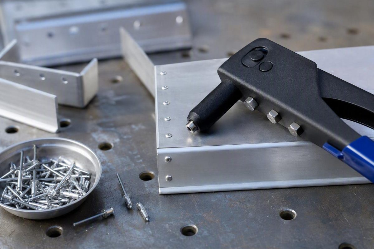
A dependable blind-riveted joint comes from compatibility and preparation—not merely squeezing until the mandrel pops. The rivet’s published grip range must cover the complete material stack, the drilled hole must follow the fastener specification, and the nosepiece and riveter must suit the selected rivet. During installation, the factory head must remain seated while the tool pulls squarely.
This guide explains how to use a riveter tool for break-mandrel blind rivets, with the main procedure focused on a manual hand riveter. It also covers cordless and pneumatic tools, inspection, troubleshooting, removal considerations, and maintenance.
First, Identify the Kind of Riveter You Have
The main procedure in this article covers a tool that installs break-mandrel blind rivets, commonly called pop rivets. These fasteners are useful when you can reach only the front of a joint. The tool operates from that accessible side while the rivet body forms behind the work.
A break-mandrel blind rivet has three visible parts:
- Body or sleeve: The hollow section inserted through the work.
- Factory head or flange: The formed head that rests on the accessible surface.
- Mandrel: The projecting pin gripped and pulled by the riveter.
This draws the layers together. At the designed endpoint of the setting cycle, the mandrel breaks. That one-sided operating principle distinguishes blind riveting from methods requiring access to both faces of the joint, as shown in this pop-rivet operating guide.
Here is a simplified identification diagram:
                 RIVETER
        ┌─────────────────────┐
        │     Nosepiece       │
        └──────────┬──────────┘
                   │ grips mandrel
                   ▼
            ───────────────►  Mandrel
                 ┌─────┐
                 │     │  Factory head / flange
ACCESSIBLE SIDE  └──┬──┘
════════════════════╪════════════════  First material layer
                    │
                    │  Body / sleeve inside drilled hole
════════════════════╪════════════════  Second material layer
                    │
BLIND SIDE          ▼
              Body forms here
              as mandrel is pulled

        Complete material stack = all clamped layers
Do not assume every tool described as a riveter follows this procedure:
-
A solid-rivet gun drives a solid rivet while a bucking bar supports and forms the opposite end. It requires rear access and a different process.
-
Some combination tools can install more than one fastener system, but each mode still requires the correct tooling and procedure.
Before proceeding, compare the tool with its manual and the fastener information. A conventional pop-rivet tool normally has a nosepiece with an opening for the projecting mandrel and an internal jaw mechanism that grips the mandrel as the handles close.
In this article, riveter, hand riveter, and pop-rivet tool mean a break-mandrel blind-rivet puller unless another tool type is named explicitly.
Choose a Compatible Rivet, Nosepiece, and Tool
Successful installation begins with a compatibility check. A rivet can pass through a hole yet still be unsuitable for the joint, and a mandrel can enter a nosepiece even when the tool lacks the required capacity.
Check all of the following before drilling:
- Correct break-mandrel blind-rivet type
- Rivet-body diameter
- Manufacturer-published grip range
- Rivet-body and mandrel materials
- Manufacturer-specified hole diameter
- Correct nosepiece or nose assembly
- Riveter capacity for that rivet diameter and material
- Enough access for the nose to sit flat
- Suitability for the workpiece materials and service environment
Measure the complete material stack. Include every sheet, bracket, reinforcement, spacer, or other layer the rivet must clamp. Do not measure only the top sheet or rely on nominal material descriptions when coatings, bends, or overlaps affect the actual thickness.
Choose a rivet whose published grip range includes the total stack thickness. Grip range is the thickness interval over which the rivet is intended to form and clamp. It is a better selection criterion than guessing from the amount of body projecting behind the work. Manufacturer troubleshooting guidance directly associates loose joints with an unsuitable grip range or oversized hole, reinforcing the need to verify both before installation (see the blind-rivet failure guide).
Obtain the required hole diameter from the selected rivet’s packaging, data sheet, or catalog entry. Do not assume the drill must exactly equal the nominal rivet diameter, and do not apply one fixed clearance to every blind rivet. The selected fastener specification should govern.
The nosepiece must match the selected rivet or mandrel specification. The mandrel must enter correctly and engage the jaws, while the tool nose must be able to bear against the factory head. Confirm the required setup from the riveter manual rather than choosing a nosepiece solely because the mandrel passes through it.
Check the riveter’s capacity chart as well. Capacity is not determined by diameter alone: rivet and mandrel material affect the force required. Large, long, steel, stainless-steel, and structural rivets may exceed the rating of a light plier-style tool. Depending on the fastener, a long-handle lever tool, lazy-tong tool, ratcheting design, cordless puller, pneumatic riveter, or another suitably rated system may be necessary. Tool geometry, access, workload, and physical effort all affect the choice, but the individual tool’s published rating remains decisive (compare common hand and battery designs).
Physical access is part of compatibility. The nosepiece must reach the factory head and sit flat against it. Check for interference from corners, channels, recesses, adjacent rivets, bends, and raised features. If another feature contacts the tool first, do not compensate by pulling at an angle. Use compatible access tooling when the manufacturer permits it, or revise the joint arrangement if the project allows.
Treat thin, soft, plastic, or brittle work cautiously. Such material can dimple, crack, crush, or permit the formed blind side to pull through. An application-specific backing washer or a rivet designed to spread load may be appropriate, but no one washer or specialized rivet is suitable for every substrate. Follow the fastener manufacturer’s application guidance and confirm that the proposed arrangement fits the available space.
Also consider the service environment. Do not assume that simply matching or mixing particular metals resolves those concerns.
Gather the Tools and Prepare the Joint
Gather the complete setup before positioning the work:
- Compatible manual, cordless, or pneumatic blind riveter
- Correctly specified break-mandrel blind rivets
- Matching nosepiece or nose assembly
- Drill
- Manufacturer-specified drill bit
- Clamps or other stable workholding
- Rule, caliper, marker, or scribe as appropriate
- Deburring tool suited to the material
- Eye protection
- Container for chips and broken mandrels
- Riveter manual
- Rivet packaging, data sheet, or catalog information
Keep the manual and rivet data at the bench. Use them to verify capacity, hole size, setup, operating precautions, maintenance, and any model-specific personal protective equipment.
Place the parts in their final alignment and clamp them so the layers cannot shift or separate while drilling and riveting. If several holes must align, plan the drilling and fastening sequence instead of drilling an unsecured stack.
Mark the rivet location. Apply the project’s approved drilling procedure to confirm that the selected location and breakthrough area are clear; this guide does not establish a universal method for checking concealed wiring, hoses, hardware, finished surfaces, or other hidden features.
Drill squarely through the complete stack using the specified hole diameter. Wear eye protection, keep the work stable, clear shavings, and follow the tool manual’s additional protective-equipment and hand-positioning instructions. Drilling chips and broken mandrels are sharp debris and should be controlled and collected (manufacturer-supported installation precautions).
Do not enlarge the opening sideways to compensate for shifted sheets. If the layers no longer align, stop and correct their position.
Deburr the opening as appropriate for the material and joint design. Remove loose chips from the accessible side, blind side where reachable, and between the layers. The sheets must be able to close together without trapped debris.
Before pulling the first rivet, verify:
- Layers are aligned in their final position.
- Work is clamped securely.
- Hole is clean and matches the selected rivet specification.
- Burrs and trapped chips have been removed.
- Total stack is within the rivet’s published grip range.
- Correct nosepiece or nose assembly is installed.
- Riveter is rated for the selected diameter and material.
- Rivet head and tool nose are fully accessible.
- The project’s required drilling-location checks are complete.
Correct a failed checkpoint before continuing. More handle force cannot repair an oversized hole, unsuitable grip range, obstructed nose, or incompatible tool.
How to Use a Manual Hand Riveter, Step by Step
The following procedure covers a conventional plier-style manual blind riveter. If your model uses a ratchet, lazy-tong linkage, rotating head, interchangeable nose assembly, or another mechanism, follow its manual where the controls or setup differ.
-
Install or select the specified nosepiece. Follow the model’s procedure for changing or selecting nose components. Secure the nosepiece as directed and test the rivet mandrel. It should enter correctly without binding and allow the jaws to engage it. Confirm that the nose can bear on the factory head without striking a nearby feature.
-
Open the handles fully. If the handles do not open normally, do not force a rivet into the tool. Follow the manual’s troubleshooting procedure for retained mandrels, debris, incorrectly fitted components, or mechanical faults.
-
Insert the rivet body fully into the prepared hole. Place the body through the complete material stack from the accessible side. Press the factory head flat against the surface. It should not rock on a burr, chip, damaged opening, or misaligned layer.
-
Slide the riveter over the mandrel. Feed the projecting mandrel into the nosepiece until the tool nose bears firmly against the rivet head. Loading the mandrel into the riveter before placing the body in the hole can also work. Whichever order you use, maintain control of the fastener and confirm that the body is fully inserted.
-
Hold the riveter approximately perpendicular to the work. Align the pulling axis with the mandrel and keep the factory head flat. On curved or irregular work, the important requirement is that the tool pull along the rivet axis while the nose bears evenly on the head.
-
Squeeze through one complete, controlled stroke. Close the handles smoothly. Do not jerk the tool, twist it, or use it as a sideways lever. Maintain contact between the nosepiece and factory head throughout the stroke.
-
Reopen fully and repeat if the mandrel has not broken. Many plier-style riveters require more than one stroke. Reopen the handles completely so the jaws can reset and grip another section of mandrel. Keep the tool nose against the head so the rivet does not lift between strokes, then make another complete pull.
-
Stop when the mandrel snaps. The break marks the end of that fastener’s pull cycle. Release the handles and withdraw the riveter straight back. Do not continue operating the handles against the remaining rivet.
-
Control and collect the broken mandrel. Depending on the model, the mandrel may remain in the nose, fall out when the handles open, or pass into a collector. Follow the tool’s ejection procedure and place the mandrel in the debris container.
The number of strokes is not universal. It depends on the riveter’s mechanism and jaw travel, as well as the rivet’s dimensions and material. Several strokes do not automatically indicate a fault. Jaw slippage, abnormal force, failure to advance, or a rivet lifting from the work does.
Use this six-point technique check during every installation:
Flange flat. Tool square. Mandrel fully engaged. Joint clamped. Complete strokes. No sideways leverage.
If one of those conditions changes while pulling, stop instead of trying to steer the rivet under load.
Using Cordless and Pneumatic Riveters
A powered riveter changes how the pulling force is produced, but not the fundamentals. The rivet type, grip range, hole, nose assembly, tool capacity, access, seating, alignment, and inspection must still be correct.
For a cordless riveter:
- Prepare the battery and tool as the manufacturer directs.
- Fit the specified nosepiece or complete nose assembly.
- Check the mandrel path or collector if the model has one.
- Insert and seat the rivet.
- Hold the tool square with its nose against the factory head.
- Operate the trigger as directed until the tool completes its pull cycle.
- Reset the tool if required and account for the broken mandrel.
Do not assume every battery riveter holds an unloaded rivet in its nose, uses suction, ejects mandrels automatically, or sends them into a collector. Those features are model-specific.
For a pneumatic riveter, verify the air system before operating the tool. The compressor, regulator, hose, and fittings must satisfy the exact model’s stated pressure and airflow requirements; both PSI and CFM are tool-specific setup values (pneumatic riveter requirements).
Follow the pneumatic riveter manual for:
- Regulated operating pressure
- Required airflow
- Air preparation and moisture control
- Approved lubricant, if any
- Hose connection and disconnection
- Pressure adjustment
- Collector operation
- Servicing
- Clearing obstructed mandrels
Do not raise pressure outside the specified range in an attempt to set an incompatible rivet. If the tool does not pull, follow its diagnostic procedure and check compatibility, nose setup, jaw condition, mandrel path, air supply, and rated capacity.
If the cordless or pneumatic model has a mandrel collector, inspect and empty it as its manual directs. If it has no collector, control and collect each mandrel by another method consistent with the tool instructions.
Choose among tool types according to practical constraints:
- Hand riveters need no battery, hose, or compressor but require physical effort.
- Cordless riveters offer mobility but depend on compatible, charged batteries.
- Pneumatic riveters require a suitable compressor, regulated air supply, fittings, and hose access.
Job volume, repetitive effort, access, rivet capacity, mobility, available power, and budget should guide the choice. The power source alone does not establish whether a joint is acceptable; compatibility, preparation, technique, and inspection remain essential.
Inspect the Rivet: The Pop Is Not the Quality Check
Mandrel breakage tells you that the pull cycle has ended. It does not prove that the selected rivet covered the correct grip range, filled the hole appropriately, clamped the layers, or avoided damaging the work.
Inspect each installation before moving on.
First, examine the factory head. It should sit evenly against the accessible surface rather than standing proud or leaning to one side. A tilted head may indicate an angled tool, uneven nose contact, debris under the flange, incomplete insertion, or obstructed access.
Next, check the joint:
- Are the layers closed together?
- Is there an unexpected gap?
- Does either part rock, rotate, or move?
- Is the factory head crushed or distorted?
- Has the surrounding material cracked, pulled through, or dimpled excessively?
- Is there an obvious incomplete mandrel break or abnormal projection?
Acceptable break characteristics depend on the rivet design and applicable project criteria.
Where the blind side is visible, compare its formation with the selected fastener manufacturer’s instructions.
When the blind side is inaccessible, do not assume that a flush-looking factory head proves correct rear formation. Use the specified fastener, a controlled installation process, and the project’s required inspection method.
A basic visual check is not a substitute. Technical guidance for other rivet systems likewise shows that acceptance depends on the joint and service conditions rather than appearance alone (joint-specific rivet acceptance considerations).
Use this pass-or-stop checklist:
- Factory head seated evenly
- Material layers closed
- No looseness, rocking, or movement
- No cracking, crushing, pull-through, or unacceptable dimpling
- No obvious incomplete setting
- Installation conforms to the fastener and project requirements
If any item fails, stop. Do not conceal the condition with paint, sealant, filing, or cosmetic trimming.
Troubleshoot Loose, Crooked, or Incomplete Rivets
Do not reduce every fault to “use a larger rivet.”
| Symptom | Possible causes | Corrective action |
|---|---|---|
| Joint remains loose after the mandrel breaks | Grip range does not cover the stack; hole is oversized or damaged; layers were not clamped together; head was not seated; nose access was restricted; tool was angled; tool lacked capacity | Stop using the joint. Verify stack thickness, rivet data, hole condition, clamping, access, and tool rating before installing a replacement. |
| Mandrel does not pull | Wrong nosepiece; jaws do not engage; worn jaws; debris; incompatible rivet; tool fault; incorrect model-specific power or air setup | Stop applying force. Follow the tool’s unloading and inspection procedure, then check the nosepiece, jaws, mandrel path, specifications, and power settings. |
| Mandrel pulls but does not break | Inadequate jaw travel or capacity; slipping jaws; unsuitable fastener; incomplete powered cycle; battery or air-supply problem | Do not cycle indefinitely. Verify the rivet and tool specifications, inspect jaw grip, and check the model’s setup and service instructions. |
| Jaws slip on the mandrel | Metal particles; worn or damaged jaws; unsuitable nosepiece; incomplete handle reset | Clean and inspect the mechanism. Replace worn service parts according to the manual rather than applying uncontrolled force. |
| Rivet head tilts or stands proud | Tool was not square; nose did not bear flat; burr or debris remained; rivet was not fully inserted; surrounding geometry blocked access | Replace the defective fastener under an approved procedure after correcting the preparation or access problem. |
| Handles are extremely hard to squeeze | Rivet diameter or material exceeds the rating; rivet requires high force; tool has insufficient leverage; mandrel binds; tool is faulty | Compare the exact rivet with the tool’s capacity chart. Use a suitably rated higher-leverage or powered tool if required. |
| Thin material cracks, crushes, or dimples | Unsuitable rivet design or diameter; poor hole; inadequate support; excessive local loading; soft or brittle substrate | Stop and reassess the material, rivet design, hole preparation, support, and any manufacturer-approved load-spreading solution. |
| Nose cannot reach a recessed rivet | Tool head is too wide or short; corner or recess prevents flat contact | Do not pull at an angle. Use a compatible access attachment or revise access when permitted by the tool and project requirements. |
| Broken mandrels obstruct the tool | Mandrel path or collector needs attention; nose setup is unsuitable; internal component is damaged | Stop operating and follow the model’s clearing and inspection procedure. |
Troubleshooting guidance associates loose joints with unsuitable grip range or hole size, incomplete setting with inadequate tool performance, and pulling problems with worn or slipping jaws. It also identifies thin or brittle substrates as applications that may require a specialized load-spreading solution. These are diagnostic categories, not universal prescriptions for a particular washer or rivet design.
A loose, crooked, visibly incomplete, or materially damaging rivet generally should not be accepted or merely trimmed. Diagnose the setup and replace the fastener if the applicable project procedure permits it.
Blind-rivet removal is not a single universal operation. Drilling or cutting can enlarge the hole, mark the surrounding surface, or distort thin material, and a loose rivet may spin rather than remain controlled. Available removal advice varies with fastener type, access, and workpiece, and even experienced users disagree about drilling loose rivets in particular applications (example of disputed removal considerations).
For that reason, follow a fastener-, tool-, or project-specific removal procedure. If no approved procedure is available, do not improvise one from a solid-rivet gun-and-bucking-bar method. After removal, the hole and surrounding material must be assessed under the project’s requirements before another fastener is selected.
Clean, Inspect, and Store the Riveter
Collect broken mandrels and drilling debris when the work is complete. Do not leave sharp metal pieces loose on the bench, floor, in a channel, or inside the finished assembly.
If the tool has a mandrel collector, empty it according to its manual. A model without a collector requires deliberate control and disposal of each broken mandrel.
Wipe dirt and loose particles from the nose and exterior. Clean only the areas and components identified by the manufacturer, using its stated procedure rather than forcing debris deeper into the mechanism.
Inspect the applicable service points:
- Nosepiece opening and threads
- Jaw grip and jaw condition
- Handle pivots and linkage
- Accessible mandrel path
- Collector and cap, where fitted
- Model-specific battery or pneumatic components identified in the manual
If the jaws slip, clean and inspect them before the next job. Replace worn or damaged service parts with compatible components according to the manufacturer’s procedure. General hand-riveter maintenance includes removing dirt and shavings, inspecting jaws, lubricating applicable mechanisms, and storing the tool in a dry place (hand-riveter maintenance guidance).
Lubricate only the specified points, using the stated lubricant and interval. Manual, cordless, pneumatic, and hydraulic-pneumatic riveters can have different maintenance requirements.
For cordless tools, follow the tool and battery documentation for charging, inspection, and storage. For pneumatic tools, follow the model instructions for air preparation, approved oil where applicable, pressure release, hose disconnection, and servicing.
Store the riveter clean and dry. Keep interchangeable nosepieces, wrenches, collectors, compatible access attachments, and manuals organized with the tool so the next setup can be verified rather than guessed.
Frequently Asked Questions
How do I choose the correct nosepiece for a pop rivet?
Use the nosepiece or nose assembly specified for the rivet and mandrel, checking both the riveter manual and the fastener information. The mandrel must enter correctly and engage the jaws, while the nose must bear flat against the factory head.
Do not choose solely by whether the mandrel passes through the opening. Also confirm that the nosepiece fits the riveter and can reach the head without interference.
How many times should I squeeze a manual riveter?
There is no universal number. A manual riveter may set a rivet in one stroke or require several complete strokes, depending on the mechanism, jaw travel, leverage, and rivet dimensions and material. Basic manual-riveter instructions likewise describe repeated squeezes until the mandrel breaks (manual riveting procedure).
Open the handles fully, make a complete controlled stroke, then reopen and repeat if the mandrel has not broken. Keep the nose against the factory head. Stop and consult the tool procedure if the jaws slip, the rivet lifts, force becomes abnormal, or the mechanism does not advance.
Does the pop mean the rivet is installed correctly?
No. The pop means the mandrel has broken and the pull cycle has ended. It does not independently verify grip range, hole quality, rear-side formation, clamping, or the absence of material damage.
Check that the factory head is seated evenly, the layers are closed and immobile, and there is no cracking, crushing, excessive dimpling, pull-through, or obvious incomplete setting. Apply any additional project-specific inspection criteria.
Why is my rivet still loose after the mandrel snapped?
Possible causes include an unsuitable grip range, an oversized or damaged hole, layers that were not clamped together, incomplete head seating, angled tool operation, obstructed nose access, or inadequate tool capacity.
Do not automatically install a larger rivet. Follow the applicable removal procedure, inspect the hole and material, identify the cause, and then select a compatible replacement.
Can a basic hand riveter install stainless-steel rivets?
Only if the specific tool’s capacity chart includes the selected stainless-steel rivet diameter and design. “Hand riveter” describes how the tool is powered, not a universal capacity.
Some long-handle or high-leverage manual tools can set rivets that exceed the rating of a light plier-style riveter. If the pull requires extreme force, stop and verify the specifications rather than extending the handles, jerking the tool, or assuming every manual riveter can complete the job.
For every installation, remember the complete sequence:
- Verify the rivet, grip range, hole specification, nosepiece, tool capacity, materials, and access.
- Align, clamp, drill, deburr, and clean the joint.
- Seat the factory head and pull with the tool square.
- Inspect the result instead of trusting the pop.
- Diagnose and replace defective fasteners under an applicable procedure.
- Clear debris, inspect wear parts, and maintain the tool as directed.
The pulling stroke is only one part of blind riveting. Reliable results come from controlling the complete process. If a rivet is loose, crooked, incomplete, or damaging the material, stop and correct the setup rather than applying more force or accepting the joint.