
Hex Head Screw: How to Identify, Measure and Specify One
Identify a hex head screw by thread, length, strength, material and standard, then check grip, hole fit and tightening conditions.
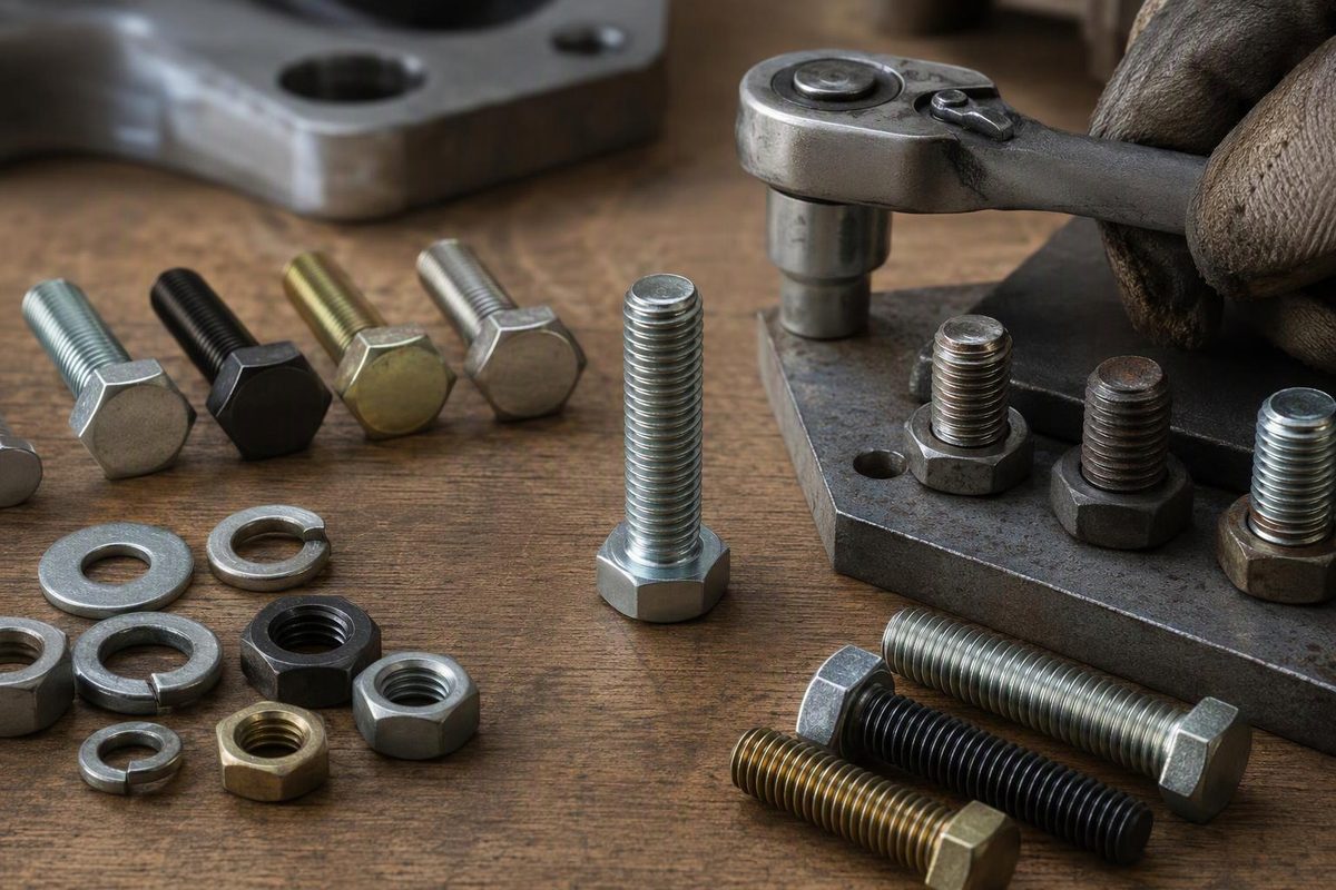
A hex head screw is an externally threaded fastener with a six-sided head driven by a wrench or socket. That identifies the drive and general form, but it is not enough information to buy a replacement. Diameter, pitch, length, thread coverage, strength, material, finish and dimensional standard can all change while the head looks much the same.
In inch-series catalogs, the part may be called a hex cap screw, hex head cap screw or hex bolt. Supplier terminology is not perfectly uniform, so order from dimensions and specifications rather than from “bolt” or “screw” alone.
What to put on the parts list
A useful callout follows this pattern:
M8 × 1.25 × 30, ISO 4017, class 10.9, zinc-plated steel
or
3/8-16 UNC × 1-1/2 in., hex cap screw, SAE Grade 5, zinc plated
Each part closes a different fit or strength question:
| Item | What it controls |
|---|---|
| Diameter and pitch | Whether the screw matches the nut or tapped hole |
| Length | Whether it reaches without bottoming or protruding excessively |
| Full or partial thread | Whether the joint bears on threads or a plain shank |
| Standard or product form | Head, body, thread-length and dimensional details |
| Grade or property class | Mechanical properties, not physical size |
| Material and finish | Corrosion behavior, compatibility and tightening friction |
Do not treat a dimensional standard as a strength grade. ASME B18.2.1 covers dimensions for several inch-series square, hex and related bolt and screw forms; the standard’s title identifies those product families but does not supply the material grade in the fastener callout (ASME). Specify the applicable ASTM or SAE grade separately.
For metric fasteners, ISO 4017 covers hexagon head screws in product grades A and B. ISO lists the 2011 edition as withdrawn and points to ISO 4017:2022 as the new version (ISO). A supplier listing or drawing should state the applicable standard rather than relying on appearance.
Measure an unknown screw in this order
Clean off dirt and loose corrosion first. Then record:
- Outside thread diameter. Measure across the thread crests with calipers. A reading near 8 mm suggests M8; one near 0.375 in. suggests 3/8 in., but diameter alone does not establish the thread.
- Pitch. Use a thread-pitch gauge. Metric pitch is the distance between adjacent crests in millimetres. Inch threads are commonly stated as threads per inch, such as 3/8-16.
- Length. On a conventional hex head, measure from the bearing surface under the head to the end, not over the head.
- Threaded length. Note whether threads run nearly to the head or stop to leave a plain shank.
- Width across flats. This selects the wrench or socket. It does not reliably identify thread diameter because standards and product forms can use different head sizes.
- Head markings and provenance. Record every line, number and manufacturer mark. Do not infer strength from plating color, head size or apparent hardness.
A nut of unknown origin is a poor thread gauge. It may start on a mismatched pitch and bind after a turn or two. Check with a pitch gauge and a known-good mating part without forcing it.
Check the joint, not just the screw
For a through-bolted joint, total the clamped material thickness, washers and nut height. Select enough length to engage all the nut’s threads, then check that the plain shank does not enter the nut and that thread runout does not hold the joint apart. Also check whether excess projection would strike a moving part or create a snag.
For a tapped hole, compare usable thread depth with screw length. Allow for the drill point, incomplete threads at the bottom, debris and any washer. A screw that bottoms can feel tight while applying little clamp load.
The clearance hole is a separate decision from nominal screw size. It must accommodate the actual shank and the required assembly tolerance. The options for one common metric size are covered in M6 clearance hole size.
Inspect the bearing surface under the head as well. Use a suitable washer when the drawing or manufacturer requires one, when a slot needs bridging or when the parent material needs a larger bearing area. A washer does not correct a burred, badly oversized or misaligned hole.
Tighten only after the specification is complete
Torque cannot be selected from “hex head screw” alone. Fastener grade, diameter, pitch, coating, lubrication, joint material and the required clamp load all matter. Lubrication can produce more clamp load at the same wrench setting, so a dry-table value should not be transferred casually to oiled or anti-seize-coated threads.
Use the equipment maker’s torque specification where one exists. Otherwise, use a torque source that explicitly matches the fastener grade, size and thread condition. The friction issue and practical tightening sequence are covered in bolt torque basics.
Before final tightening, verify that the screw turns freely by hand through the expected engagement, the head seats flat, the parts close without a gap and the socket fully engages the flats. Those checks distinguish a fastener that merely starts from one that fits the finished joint.