
Countersink Bit: Choose the Cutter and Troubleshoot Chatter
Choose a countersink bit by angle, cutting range and material, then set speed, troubleshoot chatter and check the finished screw seat.
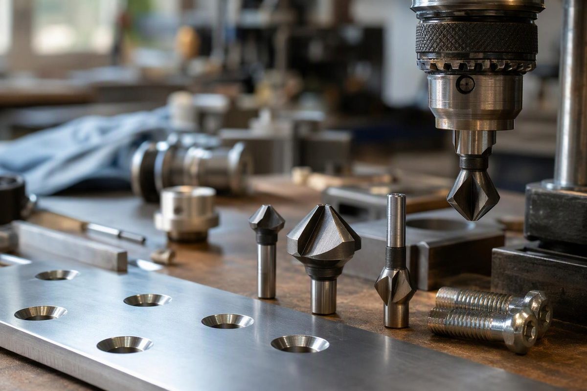
A countersink bit cuts the conical recess beneath a flat-head screw. For a metal bracket or machine plate, choose it by included angle, usable cutting diameter, cutter material and machine setup—not just the screw’s thread diameter. This guide focuses on cutter selection and running the tool without chatter.
The aim is a smooth, concentric seat at the specified depth. A screw that looks flush is a useful fit check, but it does not prove that the angle or bearing contact is correct.
Check the angle and cutting range first
The included angle is the full angle across the cone, not the angle from its side to the centerline. Match the drawing or fastener specification. Common choices are 82° for inch flat-head screws and 90° for metric ones, but verify the actual screw: Bolt Depot lists an 82° inch machine screw and a 90° M6 machine screw, for example.
Before buying, record:
- The required seat angle and finished mouth diameter.
- The existing hole diameter and stock thickness.
- The cutter’s maximum diameter, non-cutting tip diameter and shank size.
- Whether the tool is recommended for a handheld drill or requires a rigid machine.
Cutter body diameter is not automatically the finished countersink diameter. Depth determines how much of the cone enters the part. Check the maker’s sizing table, especially for zero-flute tools: M.A. Ford specifies different minimum body sizes for its Series 67 zero-flute cutters and its other countersinks when seating the same screw. Its application data illustrates why one nominal diameter is not a universal capacity rating.
For hole sizing and seat-depth geometry, use the companion guide to matching the countersink and drill bit.
Choose the cutter style for the job
| Style | Useful starting point | What to check |
|---|---|---|
| Single-flute | Machine or portable work; an alternative when a multi-flute cutter chatters | Minimum hole size and material suitability |
| Three-flute | Machine or portable countersinking; centering ability helps portable work | Maker’s speed guidance and a stable setup |
| Zero-flute | Countersinking and deburring with a single cutting edge | Actual cutting range, not just body diameter |
| Adjustable drill-and-countersink | Wood or plastic screw holes | Do not assume the assembly is suitable for steel |
These applications follow ICS Cutting Tools’ selection guidance. Flute count alone is not a guarantee of finish; the tool still needs the right speed, support and feed.
For ordinary garage-shop metal work, an HSS cutter rated for the material is a sensible starting choice. Carbide is not automatically an upgrade for a loose drill press or handheld drill. M.A. Ford’s Series 78 carbide countersinks, intended for hardened steel and other difficult materials, explicitly require rigid setups and are not recommended for handheld tools.
Set speed for the countersink—not the preceding drill
Use the cutter maker’s recommendations. M.A. Ford advises starting at the lower end of its speed range; excessive RPM can cause chatter, overheating and premature dulling.
Its conversion is:
RPM = surface speed in feet/minute × 3.82 ÷ tool diameter in inches
For example, its HSS guidance for mild steel containing 0.2–0.3% carbon is 80–100 surface feet/minute. With a 1/2-inch cutter, the lower end gives about 610 RPM. That is a chart-derived starting point, not a universal setting for every 1/2-inch countersink. Material, geometry and rigidity still matter. See the M.A. Ford speed and feed chart.
Cut a sample, then inspect
- Clamp and align the work. Support it close to the hole without obstructing the cutter. Wear eye protection, remove the chuck key and do not wear gloves while operating a drill press. Contain long hair and loose clothing. Stop the machine completely before adjustments, measurements or chip clearing; these precautions are covered in the University of Saskatchewan drill-press procedure.
- Test on matching scrap. Use the same material, thickness and hole size. Apply material-appropriate cutting fluid where recommended.
- Feed steadily and stop short. Stop the spindle, clear chips with a brush and check the seat before taking another small cut. Do not use screw-tightening torque to force the head into an unfinished seat.
- If a ridged or polygonal pattern appears, stop. Check clamping, cutter sharpness, tool overhang and spindle play. Do not continue with loose or faulty equipment. Reduce excessive RPM rather than immediately pressing harder. M.A. Ford recommends beginning feed at the low end and increasing gradually within the tool’s limits. If a multi-flute cutter still chatters in a sound setup, consider the single-flute alternative described above.
- Inspect before repeating. Check mouth diameter against the drawing, surface finish, concentricity and screw-head position. Set a depth stop from the acceptable sample, then verify the first finished-part hole.
If the seat reaches the back face of thin stock before meeting the required dimensions, stop and revisit the joint design. Cutting deeper cannot replace the material already removed.