
1/4-20 Tap Drill Size, but 7/32 Is Oversized
A 7/32-in. hole may still take a shallow thread, but that does not make the bit a standard or equivalent 1/4-20 substitute.
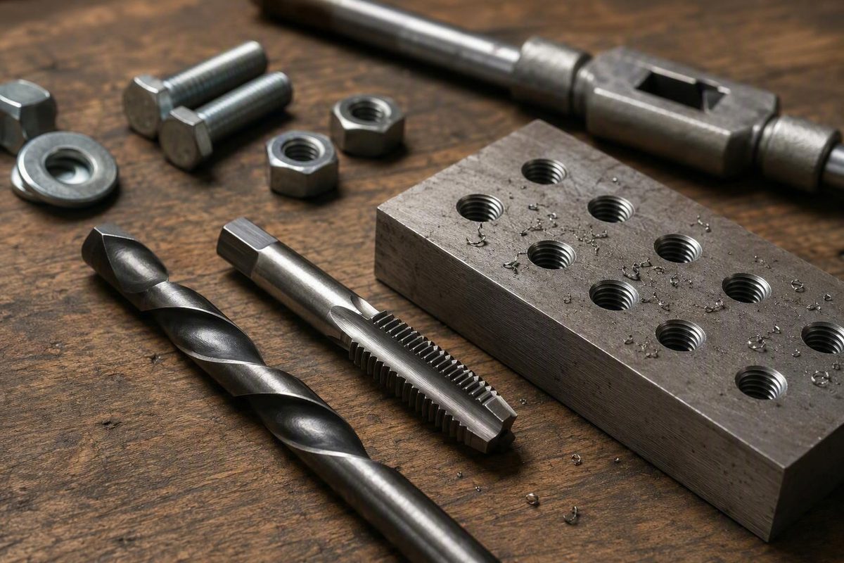
Quick answer: use a No. 7 drill for a 1/4-20 cutting tap
Answer: For a conventional 1/4-20 UNC cutting tap, use a No. 7 drill bit. Its nominal diameter is 0.2010 inch, or approximately 5.11 mm, according to the 6G Tools standard inch tap-drill chart.
If your drill index does not include numbered bits, 13/64 inch is the closest common fractional substitute. It measures 0.2031 inch, making it approximately 0.0021 inch larger than No. 7—not an exact equivalent. RivCut’s decimal drill chart documents those dimensions and the difference.
Scope note: This answer applies to a conventional cutting tap, which removes material. It does not establish the correct hole size for a thread-forming or roll tap, which displaces material and requires guidance appropriate to the specific tool and material.
| Choice | Nominal diameter | Metric equivalent | Role for 1/4-20 |
|---|---|---|---|
| No. 7 | 0.2010 in | 5.11 mm | Preferred chart size for a conventional cutting tap |
| 13/64 in | 0.2031 in | 5.16 mm | Closest common fractional fallback; slightly oversized |
| 7/32 in | 0.2188 in | 5.56 mm | Oversized for normal 1/4-20 tapping |
| 1/4 in | 0.2500 in | 6.35 mm | A chart-dependent close-fit or nominal clearance option, not a normal tap drill |
The practical choice is straightforward: use No. 7 when the job calls for the customary chart size. Use 13/64 inch only as a deliberate substitute when its slightly larger diameter—and correspondingly lower engagement—is acceptable.
Published tap-drill charts commonly base their selections on approximately 70–75% thread engagement or depth. That percentage is a chart basis, not a guaranteed result. The finished hole and thread can vary with drill tolerance, runout, tool condition, tap geometry, thread limits, workpiece material, and process control.
What 1/4-20 and No. 7 actually mean
The designation 1/4-20 contains two pieces of information:
- 1/4 is the thread’s nominal major diameter in inches.
- 20 means 20 threads per inch, commonly abbreviated 20 TPI.
The thread is UNC, or Unified National Coarse. Older or simplified charts may label it NC. It is not the same as the finer 1/4-28 UNF thread, which requires a different tap-drill selection. The nominal-diameter and TPI meanings are also summarized in Sundi Cutting Tools’ 1/4-20 drilling guide.
The nominal quarter-inch dimension describes the approximate major diameter of the external thread. It does not mean that the pilot hole for the internal thread should be drilled to 1/4 inch.
A cutting tap needs material along the wall of the pilot hole. As the tap advances, its cutting edges remove and shape that material to create the internal thread. If the starting hole is already as large as the fastener’s nominal outside diameter, too much of the necessary material has been removed.
That is why the normal 1/4-20 tap drill is smaller than 1/4 inch: the drill creates the starting hole, and the tap cuts the thread into the remaining wall.
No. 7 is a numbered drill designation. It does not mean:
- seven drill bits;
- a 7-inch or 7 mm drill;
- tap number seven;
- a fraction that should be estimated by eye; or
- a size obtained by dividing another dimension by seven.
Number drills form their own size series. Drill indexes may also contain fractional, lettered, and metric bits. Those systems overlap closely in places, but nearby designations are not necessarily identical.
Decimal diameter is the reliable basis for comparison:
- No. 7 is 0.2010 inch.
- 13/64 inch converts to 0.203125 inch, commonly rounded to 0.2031 inch in drill charts.
The labels look unrelated, but the decimal values show that the two sizes are close while remaining dimensionally different.
Likewise, 5.11 mm is simply the metric conversion of the No. 7 drill’s nominal diameter. It does not make 1/4-20 a metric thread. The thread remains an inch-series UNC thread with 20 threads per inch.
A correctly sized 5.1 mm drill is close to the nominal No. 7 diameter. As with any substitute, compare its actual diameter with the job requirements rather than assuming that a rounded metric designation is exact.
Why tap-drill size is a balance, not just a lookup number
Greater engagement means that the tap has created a deeper thread profile in the available material; lower engagement means a shallower profile.
Many conventional tap-drill charts select a starting hole intended to produce approximately 75% thread depth. That figure represents a practical compromise, not a universal ideal.
A smaller pilot hole leaves more material for the tap to remove. It generally:
- increases tapping torque;
- increases the load on the tap;
- makes lubrication and chip control more consequential;
- raises the risk of binding or tap breakage; and
- may produce greater engagement if the rest of the process is controlled.
A larger pilot hole leaves less material for the tap. It generally:
- reduces tapping effort;
- reduces the amount of material the tap must remove;
- creates a shallower thread profile; and
- reduces engagement and potential holding capability.
The drill’s label does not reveal the exact finished engagement.
Cutting-tool manufacturer Guhring provides a useful broader perspective. Its technical guidance says many conventional charts aim for approximately 75% thread, but it suggests 60–70% for many applications to improve tap life. Guhring also states that a 100% thread is only 5% stronger than a 75% thread while requiring three times the tapping torque. That is manufacturer guidance illustrating the torque-versus-engagement tradeoff, not a strength guarantee for a particular joint. See Guhring’s Tap Drill Calculator and thread-percentage guidance (accessed August 13, 2026).
In practice, tap-drill selection balances four concerns:
- Engagement: Does the hole leave enough material to create the required thread profile?
- Tapping load: Can the tap cut the material without excessive torque?
- Tool life and reliability: Is the setup unnecessarily hard on the tap?
- Application requirements: Does the finished thread satisfy the drawing, tolerance, process, and performance requirements?
For routine shop work, the No. 7 chart recommendation is a sensible starting point. It should not override an engineering drawing, customer requirement, specified thread tolerance, governing standard, or current tap-manufacturer recommendation.
Can 13/64 inch substitute for a No. 7 drill?
Yes. 13/64 inch is commonly listed as the closest fractional substitute for a No. 7 drill when tapping 1/4-20 with a cutting tap. It is a practical fallback, not an exact equivalent.
The dimensional comparison is:
- No. 7: 0.2010 inch
- 13/64 inch: 0.2031 inch
- Rounded difference: 0.0021 inch
The customary pairing of 1/4-20 with No. 7 and 13/64 inch appears in the Lincoln Machine tap-drill chart, which identifies No. 7 as the primary drill and 13/64 inch as the closest fractional size.
Because 13/64 inch is slightly larger, it removes slightly more material before tapping. The tap therefore cuts a somewhat shallower profile than it ordinarily would in a nominal No. 7 hole. All else being equal, that generally means slightly less engagement and somewhat easier tapping.
For many general-purpose holes, the difference may be acceptable when the job does not mandate a particular drill size and slightly reduced engagement is permitted. Suitability still depends on material, loading, available thread length, required fit, and the consequences of failure.
Use the specified No. 7 drill—or whatever size the governing documentation requires—for tightly controlled, highly loaded, customer-specified, or critical work.
| Drill | Decimal diameter | Verdict for a standard 1/4-20 cutting tap |
|---|---|---|
| No. 7 | 0.2010 in | Preferred general chart size |
| 13/64 in | 0.2031 in | Practical fractional fallback; slightly lower engagement |
| 7/32 in | 0.2188 in | Materially oversized; not the normal substitute |
| 1/4 in | 0.2500 in | Clearance-size option, not a normal tap-drill hole |
The difference between No. 7 and 13/64 inch is only a few thousandths. The jump to 7/32 inch is much larger: 7/32 inch is approximately 0.0178 inch larger than No. 7. It should not be grouped with 13/64 inch as though both were equally close substitutes.
One easy typo deserves mention: the fallback is 13/64 inch, not 13/16 inch. A 13/16-inch drill is far too large for this operation.
Avoid three common mix-ups: clearance holes, 7/32, and 1/4-28
Several nearby-looking sizes appear on drill and tap charts, but they serve different purposes. The most important distinction is between a tap-drill hole and a clearance hole.
A tap-drill hole is intentionally smaller than the fastener’s nominal diameter. It preserves material that the tap will cut into an internal thread.
A clearance hole is intended to let the fastener pass through the part so it can engage threads or a nut elsewhere. Its purpose is not to hold an internal thread in that hole.
An East Tennessee State University reference chart separates those operations: it lists No. 7 at 0.2010 inch as the 1/4-20 UNC tap drill, while listing letter E or 1/4 inch as close-fit clearance options. The same chart lists No. 3 at 0.2130 inch for 1/4-28 UNF and advises users to consult applicable industry or regulatory standards. See the ETSU tap-drill and clearance-hole chart.
A 1/4-inch drill can therefore appear on a chart when the objective is to let a nominal quarter-inch fastener pass through. It is not the normal drill for creating a 1/4-20 internal thread. Drilling the full nominal diameter before tapping removes the wall material needed for normal thread formation.
The second mix-up is 7/32 inch. At approximately 0.2188 inch, it is notably larger than the 0.2010-inch No. 7 drill. A tap may still mark or cut a shallow profile in that hole, but that does not make 7/32 inch the standard or equivalent substitute for 1/4-20. The resulting engagement would be lower.
The third mix-up involves pitch:
- 1/4-20 UNC has 20 threads per inch and commonly uses No. 7 at 0.2010 inch.
- 1/4-28 UNF has 28 threads per inch and commonly uses No. 3 at 0.2130 inch.
Some charts show 7/32 inch as the fractional option for 1/4-28. A reader scanning the wrong row can therefore transfer that value mistakenly to 1/4-20.
| Intended operation | Common chart selection | Purpose of the hole |
|---|---|---|
| Tap 1/4-20 UNC | No. 7, 0.2010 in | Leaves material for a 20-TPI internal thread |
| Tap 1/4-28 UNF | No. 3, 0.2130 in | Leaves material for a 28-TPI internal thread |
| Quarter-inch clearance hole | 1/4 in may be listed as a close-fit option | Lets the fastener pass through rather than creating threads |
Clearance-hole recommendations vary with fastener tolerance, desired fit, and governing specification. The point is not that every quarter-inch clearance hole must be exactly 1/4 inch; it is that a clearance-hole value must not be substituted for a tap-drill value.
Before drilling, read the complete tap marking. Confirm both the nominal diameter and the threads per inch rather than stopping at “1/4.”
When the standard No. 7 answer may not control the job
The first question is not merely “What thread size?” It is also “What kind of tap?”
A cutting tap removes material to generate the thread. A thread-forming tap, also called a roll or form tap, displaces material instead of cutting it away. Those two processes do not automatically use the same starting-hole size.
The evidence supporting No. 7 concerns conventional 1/4-20 cutting taps. It does not establish No. 7 as the correct drill for a 1/4-20 forming tap. Guhring’s calculator treats cutting and forming taps as separate categories, reinforcing the need to select guidance for the actual process rather than transferring a cutting-tap chart value to a forming tap.
If you have a forming tap, identify its manufacturer and exact series, then use the current chart or calculator for that tool and workpiece material.
Even with a cutting tap, drill selection can be affected by:
- desired thread percentage;
- workpiece material;
- tap type and geometry;
- required thread tolerance;
- hole depth and usable thread depth;
- tool-life priorities;
- required strength or performance; and
- a controlling drawing or process specification.
Hard or difficult-to-machine material can make tapping torque, lubrication, chip behavior, and tool life more important. That does not justify automatically enlarging every hole in such material by a fixed amount. Use material-specific manufacturer guidance where available.
Hole geometry also matters. A through hole extends through the part, while a blind hole stops within it.
For a blind hole, confirm before drilling:
- the required full-thread depth;
- the tap’s lead or chamfer allowance;
- the total drilled depth;
- chip-management needs; and
- adequate clearance at the bottom.
The correct allowance depends on the tap and the job, so consult the toolmaker’s data rather than relying on one universal rule.
A disciplined selection path is:
- Confirm whether the tap cuts or forms the thread.
- Verify that the designation is 1/4-20, including 20 TPI.
- Check the drawing, job sheet, customer requirement, or governing standard for a specified drill size.
- Identify the material and whether the hole is through, blind, or unusually deep.
- Use the chart or manufacturer recommendation that matches those conditions.
Testing an unfamiliar setup on scrap can reveal obvious issues with alignment, lubrication, chip handling, or tapping effort. It does not prove that the resulting thread is suitable for a critical component.
Treat work as critical when thread failure could contribute to injury, major equipment damage, or loss of required performance. Such work requires the applicable engineering requirements, inspection method, and qualified process—not merely a generic tap chart.
A practical shop checklist for drilling and tapping 1/4-20
This is a general shop checklist, not a complete engineered procedure for every material, machine, tap style, or critical joint. Manufacturer guidance supporting straight alignment, suitable cutting fluid, chip control, and scrap testing is summarized in the Sundi Cutting Tools guide.
-
Verify the complete thread designation and tap type. Confirm that the intended thread is 1/4-20 UNC and that the tool is a cutting tap before relying on the No. 7 recommendation. Read the markings rather than identifying a tap by appearance.
-
Verify the drill. Check for the No. 7 marking or measure the bit when identification or accuracy is uncertain. Do not assume a nearby-looking fractional drill has the same diameter. If using 13/64 inch, treat it as a deliberate, slightly larger substitute.
-
Locate and support the work. Mark the intended hole location using a method appropriate to the material and required accuracy. Support and secure the part so it does not move unexpectedly during drilling.
-
Drill as straight as the setup allows. Use the available equipment and setup to maintain alignment.
-
Prepare the entrance appropriately. Remove burrs and, where appropriate, lightly prepare the opening so the tap can start cleanly. Do not assume one chamfer dimension is correct for every tap, material, or drawing.
-
Use a suitable cutting fluid or lubricant. Select a product appropriate to the workpiece, tap, and manufacturer’s instructions. No single fluid is best for every material or tapping process.
-
Maintain tap alignment. Start the tap in line with the drilled hole. Where the setup permits, an appropriate alignment aid can help prevent a crooked start.
-
Manage chips according to the tool and material. Chip behavior varies among tap styles and workpiece materials. Follow the tap manufacturer’s instructions rather than applying one universal forward-and-reverse routine to every hand tap, spiral-point tap, spiral-flute tap, or machine process.
-
Plan blind-hole depth before tapping. Confirm total drilled depth, required full-thread depth, tap lead, chip space, and bottom clearance. Do not assume that drilling to the specified thread depth automatically provides the same length of usable full thread.
-
Stop if effort becomes abnormal. Do not simply apply more force. Pause or withdraw as appropriate for the tap style, then investigate pilot-hole size, alignment, lubrication, chip packing, bottoming, wear, or damage.
-
Inspect the finished thread. An intended fastener can provide a basic functional check for ordinary shop work. Use an appropriate thread gauge when a specified fit or class must be verified.
Preflight check:
- [ ] No. 7 drill—or the specified alternative—is selected
- [ ] 20 TPI is confirmed
- [ ] Cutting tap is confirmed
- [ ] Workpiece is located, supported, and secured
- [ ] Drill and tap can be held straight
- [ ] Material-appropriate fluid is available
- [ ] Chip-management method matches the tap
- [ ] Blind-hole depth and bottom clearance are adequate
- [ ] Drawing and manufacturer instructions have been checked
Frequently asked questions
What size drill bit do I need for a 1/4-20 tap?
For a conventional 1/4-20 UNC cutting tap, use a No. 7 drill, nominally 0.2010 inch or about 5.11 mm. The American Fastener tap-and-drill chart also lists No. 7 at 0.2010 inch for 1/4-20 coarse thread.
Can I use a 13/64-inch drill instead of a No. 7?
Yes, when the job permits a slightly larger starting hole and somewhat lower engagement. A 13/64-inch drill is a common fractional fallback, but it is not identical to No. 7. The Bolt Depot tap-and-drill table lists both No. 7 and 13/64 inch for 1/4-20 on a 75%-thread-depth basis.
Can I use a 1/4-inch or 7/32-inch drill for a 1/4-20 tapped hole?
Neither is the normal choice. A 1/4-inch drill is associated with a clearance-size hole, while 7/32 inch, at approximately 0.2188 inch, is substantially larger than the No. 7 tap drill and would produce a shallower thread. The distinction between tap and clearance sizes is shown in the ETSU chart cited above.
Does a 1/4-28 tap use the same drill as a 1/4-20 tap?
No. Common charts list No. 7 at 0.2010 inch for 1/4-20 and No. 3 at 0.2130 inch for 1/4-28. The Lincoln Machine chart also shows 7/32 inch as the fractional option for 1/4-28—not 1/4-20.
Is No. 7 also the correct drill for a 1/4-20 forming tap?
Do not assume so. No. 7 is the customary chart answer for a conventional 1/4-20 cutting tap. A forming tap displaces material and requires hole guidance appropriate to the exact tap, material, and desired thread condition. Use the current chart or calculator supplied by the forming-tap manufacturer.
Final takeaway: For a standard 1/4-20 UNC cutting tap, start with a No. 7 drill at 0.2010 inch, approximately 5.11 mm. A 13/64-inch drill at 0.2031 inch is the practical fractional fallback, but it is slightly larger and generally produces somewhat less engagement. Those dimensions and the substitution are documented in RivCut’s decimal drill chart cited above. Verify 20 TPI, do not confuse a tap-drill hole with a quarter-inch clearance hole, and follow drawing- or manufacturer-specific guidance for forming taps, unusual materials, blind or deep holes, and critical work.