
2 Key 1350 U-Joint Dimensions and Fit Checks
For a standard equal-axis 1350, four cap diameters near 1.188 in and two equal spans near the nominal 3.625 in width are consistent with the common configuration.
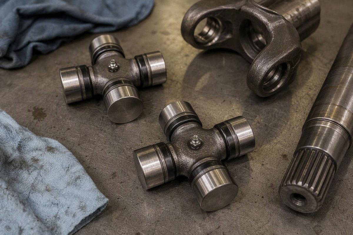
Reviewed August 18, 2026
Technical review note: The dimensions below were cross-checked across manufacturer measuring guidance, specialist identification charts, and part-specific third-party listings. The available documentation does not establish one universal manufacturing tolerance for every joint sold under the 1350-series label.
The short answer: nominal 1350 U-joint dimensions
Commonly listed standard 1350 U-joint dimensions
- Bearing-cap diameter: 1.188 inches nominal
- Fractional equivalent: 1 3/16 inches
- Approximate mathematical conversion: 30.18 mm
- Width: about 3.625 inches nominal
- Fractional equivalent: 3 5/8 inches
- Approximate mathematical conversion: 92.08 mm
- Configuration covered here: standard equal-axis, external-lock or outside-snap-ring joint
These figures are an identification starting point, not a universal fit guarantee. A third-party listing for the Spicer 5-178X specifies 3.625 inches in both directions, four 1.188-inch caps, and outside-snap-ring retention.See the listed Spicer 5-178X dimensions
The bearing-cap diameter is the outside diameter of the cylindrical bearing cap, also called a bearing cup, fitted over each trunnion of the cross. Measure the cap—not the exposed center cross or trunnion.
The width is the applicable span across one axis of the assembled joint. Depending on the part and chart, that figure may be described as outside-cap width, overall width, installed width, cross width, outside-snap-ring dimension, or lock-up width. Those labels do not always refer to identical measurement points.
The metric figures above are mathematical conversions of the nominal inch dimensions, rounded to two decimal places. They are not separate manufacturer-issued metric specifications.
Some identification charts list a 1350 width of 3.622 inches rather than 3.625 inches. That small difference is a reason to check the exact retention design and dimensional drawing—not a reason to choose a replacement solely by whichever decimal is closest.
In practical terms, four equal caps near 1.188 inches and equal cross dimensions near 3.625 inches are consistent with the common standard 1350 configuration. Confirmation still requires the cap type, retention system, yoke interfaces, and chart measurement basis to agree.
What the dimensions describe—and why terminology matters
U-joint dimensions sound straightforward until two charts use different names for the same general span—or the same name for different reference points.
A bearing cap and bearing cup refer to the same cylindrical component in the listings used here. Its outside diameter is one of the primary identification measurements.
Do not substitute the diameter of the trunnion or exposed cross.
Width terminology needs more care:
- Outside-cap width means the span from the outside face of one installed cap to the outside face of the opposite cap.
- Overall width often means the same outside-to-outside span, but the dimensional drawing must confirm that.
- Cross width is a general catalog term for the span along one axis.
- Installed width may describe the joint after it is located by the yoke and retainers.
- Outside-snap-ring dimension describes a dimension associated with an outside-lock arrangement, but suppliers do not always label its reference points identically.
- Lock-up width is the span established by the applicable grooves, rings, tabs, or retaining surfaces.
The retention geometry determines which measurement matters. Summit Racing’s identification guidance, for example, tells readers to measure smooth caps across their outside faces and grooved caps between their snap-ring grooves.Review the cap-type and width-measurement guidance
In one common external-lock arrangement, the bearing caps are smooth. Snap rings fit into grooves machined in the yoke ears and seat against the ends of the caps, preventing lateral movement. In an inside-snap-ring design, by contrast, the grooves are machined into the caps and the applicable lock-up width is measured between those cap grooves.
Do not assume that every chart using the term “outside lock” reports the same reference dimension. Some outside-lock tables describe a groove-related or installed lock-up span, while other sources list an outside-cap span. The drawing attached to the exact part must decide which surfaces to measure.
Use this sequence:
- Determine whether the caps are smooth or grooved.
- Locate the grooves: in the caps, in the yoke ears, or elsewhere.
- Identify where the clips, rings, straps, plates, tabs, or other retainers act.
- Read the candidate part drawing and note exactly where its dimension arrows begin and end.
- Measure the existing joint or yoke using that same convention.
- Compare like with like.
The three important references can be visualized separately:
                 A — CAP DIAMETER
                    ↕
              ┌───────────┐
              │   CAP     │
              └───────────┘

B — OUTSIDE-CAP SPAN
   outside face  ◄────────────────►  outside face

C — LOCK-UP SPAN
   retaining reference  ◄────────►  retaining reference
A is measured across the cylindrical outside surface of one bearing cap. B is the outside face-to-outside face span across opposing installed caps. C is measured between the applicable grooves or locating surfaces identified by the exact chart.
B and C should never be collapsed into one unlabeled “width” dimension. Even when their published values are close, they describe different physical references.
The essential fitment rule is that cap diameter, width convention, and retention style must be considered together. Matching two headline numbers is insufficient if the caps, clips, or locating surfaces differ.
How to measure an unknown U-joint accurately
Use a digital or dial caliper. A micrometer is also suitable where access permits. Spicer recommends a caliper or micrometer and organizes its measuring guidance by joint and retention style.
A ruler or tape can provide a rough sorting measurement, but it is not the right tool for distinguishing dimensions separated by only a few thousandths of an inch.
Whenever possible, make the final identification measurements with the joint clean and accessible on a bench.
-
Clean the measurement surfaces. Remove loose rust, dirt, dried grease, paint buildup, and burrs. Do not grind or file a cap simply to obtain an expected reading; doing so changes the surface being measured.
-
Inspect all four bearing caps. Determine whether each cap is smooth or contains a machined snap-ring groove. Look for external clips, internal clips, straps, U-bolts, plates, tabs, bolt holes, or other retaining features.
-
Locate the retaining grooves. Do not use “grooved” without identifying which component contains the groove. A ring may fit a groove in the cap or in the yoke ear, and those arrangements call for different measurement references.
-
Identify the retention style before measuring width. Establish where the joint is located laterally in the yoke. This narrows the applicable chart family and prevents an outside-cap measurement from being compared with an unrelated lock-up dimension.
-
Check the measuring tool. Wipe the jaws, close them gently, and verify zero. Confirm a micrometer’s zero using its normal procedure.
-
Measure cap A. Place the jaws squarely across the cylindrical outside diameter. Avoid corrosion scale, seal lips, burrs, and visibly deformed edges. Record the reading immediately.
-
Measure caps B, C, and D. Measure every cap rather than assuming that opposite caps—or all four caps—are equal. Mark the caps or sketch their positions so each reading remains associated with the correct location.
-
Measure axis 1. If the exact chart calls for outside-cap width, measure from the outside face of one installed cap to the outside face of the opposite cap. Keep the caliper aligned with the axis rather than diagonally across the joint.
-
Measure axis 2. Rotate the joint and repeat across the other pair of caps.
-
Record the lock-up span when required. If the chart identifies the joint by a groove-to-groove or retaining-surface dimension, measure that span instead of substituting the outside-cap reading.
-
Repeat questionable readings. If the number changes as the tool is repositioned, check for cocked jaws, cap damage, rust scale, burrs, or a loose cap. Record the most repeatable reading and note any damaged surface.
-
Compare the results with the exact candidate drawing. Confirm what each dimensional arrow touches. Do not compare an outside-cap reading with a groove-to-groove, yoke-groove, or installed lock-up value unless the product documentation expressly equates them.
For the common equal-axis 1350 configuration, four cap diameters near 1.188 inches and two equal spans near the applicable 3.625-inch nominal width are consistent with a standard 1350. Unequal cap diameters or opposing spans are a prompt to investigate a conversion joint rather than average the readings.
A small discrepancy does not by itself prove wear, identify a tolerance, or establish interchangeability. Corrosion, damaged edges, tool alignment, nominal rounding, and different measurement conventions can all affect the comparison.
Use a worksheet like this:
| Identification field | Recorded value |
|---|---|
| Cap A diameter | |
| Cap B diameter | |
| Cap C diameter | |
| Cap D diameter | |
| Axis 1 width or lock-up span | |
| Axis 2 width or lock-up span | |
| Cap style: smooth or grooved | |
| Groove location | |
| Retention style | |
| Width measurement basis | |
| Yoke location | |
| Visible joint part number | |
| Vehicle or driveline notes |
If the joint is missing and only the empty yoke is available, record:
- the diameter of each cap seat;
- the spacing between the relevant locating or retaining surfaces;
- the yoke style;
- groove or tab locations;
- strap, U-bolt, or bolt-hole arrangement;
- the driveshaft end or component where the yoke is installed.
Compare those readings with an exact supplier or manufacturer drawing. The nominal series name does not replace confirmation of the physical interfaces.
Why some charts say 3.622 inches instead of 3.625
Most listings used for the common standard 1350 configuration report 3.625 inches. Several identification charts instead report 3.622 inches. The published difference is 0.003 inch.
For example, Driveshaft Specialist’s outside-lock table lists 1.188-inch caps and a 3.622-inch width while describing the size approximately as 1 3/16 by 3 5/8 inches. Its instructions use a groove-related measuring convention for that outside-lock table.See the 3.622-inch chart and its measurement guidance
The available evidence does not supply a universal manufacturer tolerance proving that every 3.622-inch listing and every 3.625-inch listing are interchangeable. It also does not establish one universal cause for the difference.
Possible explanations to investigate include:
- decimal treatment of a nominal fractional dimension;
- exact-part variation within a broadly named series;
- an installed or lock-up span being compared with an outside-cap span;
- different snap-ring or retaining geometry;
- chart conventions carried over from different applications.
These are plausible explanations, not established conclusions. The exact dimensional drawing and retention arrangement must resolve the comparison.
Close decimals do not make different reference points equivalent.
Use this decision rule when a reading is near either published width:
- Verify whether the caps are smooth or grooved.
- Identify where the snap-ring grooves are located.
- Confirm the clip or retention design.
- Read the labels and arrows on the exact candidate drawing.
- Check the visible part number, if available.
- Confirm the required snap rings and their locating surfaces.
- Measure the yoke’s cap seats and applicable spacing.
- Order only after the joint, retainers, and yoke match the same specification.
For a concise shop answer, about 3.625 inches remains the appropriate nominal width for the common standard external-lock 1350 configuration. Treat 3.622 inches as a fitment caveat requiring an exact-part comparison.
1350 versus 1310, 1330, 1355, and 1410 dimensions
A U-joint series cannot be distinguished reliably by width or cap diameter alone. Both measurements must be considered with the cap and retention design.
The following figures are common listed dimensions, not universal manufacturing tolerances:
| Series | Common listed cap diameter | Common listed width | Identification note |
|---|---|---|---|
| 1310 | 1.062 in | about 3.219 in | Smaller caps and a narrower listed span |
| 1330 | 1.062 in | about 3.622 in | Listed width can be very close to a 1350 |
| 1350 | 1.188 in | about 3.625 in | Common external-lock nominal configuration |
| AAM 1355 | 1.188 in | 3.622 in | Very close to the listed 1350 dimensions |
| 1410 | 1.188 in | about 4.188 in | Same listed cap diameter as 1350 but substantially wider |
The 1310, 1330, 1350, and 1410 entries are supported by a commonly used third-party identification chart.Compare the listed series dimensions
The AAM 1355 entry comes from a separate specialist comparison listing 1 3/16-inch caps and a 3.622-inch installed width, versus 3.625 inches for the compared Spicer 1350.Review the listed 1350 and AAM 1355 dimensions
The most important comparison is 1330 versus 1350. Their commonly listed widths differ by only a few thousandths of an inch, while their standard listed cap diameters differ more clearly.
A joint near 3.625 inches wide with approximately 1.062-inch caps is therefore more consistent with the listed 1330 configuration than with a standard 1350. Width alone could point to the wrong series.
The opposite lesson appears when comparing 1350 and 1410. Both commonly use a listed 1.188-inch cap diameter, but the 1410 is listed at about 4.188 inches wide. Cap diameter alone would fail to distinguish them.
The 1350-versus-1355 comparison deserves particular caution. One specialist source reports the same nominal cap diameter and only a 0.003-inch difference in installed width. It also notes that snap-ring thickness may require attention when considering substitution. That does not establish an unconditional interchange rule.
A useful series comparison therefore needs at least:
- all four cap diameters;
- the applicable width across both axes;
- cap and groove location;
- clip or retention style;
- the measurement convention used by the chart;
- yoke cap-seat diameter and locating geometry.
Only after those features agree does the series number become dependable shorthand.
Standard joints versus conversion U-joints
A standard equal-axis U-joint normally presents the same cap diameter and span in both cross directions. A conversion joint, also called a combination joint, deliberately uses different dimensions on opposing axes so unlike driveline components can be connected.
That is why measuring one cap or one direction is insufficient.
A commonly listed 1310-to-1350 conversion combines approximately:
- 1310 axis: 3.219-inch span with 1.062-inch caps;
- 1350 axis: 3.625-inch span with 1.188-inch caps.
A listed 1330-to-1350 conversion can be harder to recognize because both axes may be about 3.625 inches wide. One axis may use 1.062-inch—or another application-specific 1330—caps, while the 1350 axis uses 1.188-inch caps.
Conversion charts also include combinations connecting 1350 dimensions with 3R, Dodge 7290, and 1410 components. One such chart identifies the typical 1350 side as 3.625 by 1.188 inches with outside-snap-ring retention.See listed conversion-joint dimensions involving 1350 components
The practical rules are simple:
- Measure all four caps.
- Measure both axes.
- Record which axis fits which yoke.
- Identify the driveshaft end being measured.
- Do not copy only the 1350 half of a conversion-joint specification into an order for a standard equal-axis joint.
- Check both ends of the driveshaft independently.
Physical measurement is particularly important on modified vehicles. A transmission, transfer case, axle, pinion yoke, slip yoke, flange, or driveshaft may have been changed during the vehicle’s service life. An application lookup may describe the original configuration rather than the components now installed.
If one axis has two 1.188-inch caps and the other has two smaller caps, do not average the readings. Record the two axes separately and search for the complete dimensional pattern.
Likewise, do not infer the capability of the complete conversion joint solely from the dimensions on its 1350 side. Suitability depends on the complete joint, both connected components, and the specific application.
What the Spicer part-number examples do—and do not—confirm
Several Spicer references illustrate why the 1.188-by-3.625 description is widely associated with 1350-series joints. The available pages, however, are third-party listings or technical articles rather than a single universal manufacturer tolerance drawing.
The Spicer 5-178X is listed by Denny’s Driveshaft as a greaseable, outside-snap-ring 1350 joint with 3.625-inch dimensions in both directions and four 1.188-inch bearing caps.Review the third-party 5-178X listing
The Spicer 5-1350-1X is listed by Dana Pro Parts as a greaseable 1350/SPL30 OSR-style joint with a 3.625-inch outside-snap-ring dimension and 1.188-inch bearing caps.Review the third-party 5-1350-1X listing
Currie Enterprises separately lists 5-1350X as its standard 1350 reference and gives a 3.625-inch cross width with 1.188-inch caps.See the listed 5-1350X reference and dimensions
These examples confirm that the same nominal dimensions appear across multiple references. They do not prove that 5-178X, 5-1350X, and 5-1350-1X can be substituted in every application.
Before substituting one part number for another, compare:
- greaseable or non-greaseable construction;
- grease-fitting location and accessibility;
- cap construction;
- seal design;
- retention arrangement;
- snap-ring requirements;
- application notes;
- current dimensional drawings;
- supersession or service information attached to the exact part.
Nominal cap diameter and width answer the dimensional-identification question. They do not establish identical internal construction, materials, lubrication requirements, or application approval.
If the existing part number is legible, retain it as a cross-reference input even after the nominal series appears to be known.
Final fitment checklist before ordering or installation
Before ordering a replacement, confirm:
- [ ] Cap A diameter
- [ ] Cap B diameter
- [ ] Cap C diameter
- [ ] Cap D diameter
- [ ] Axis 1 width or lock-up span
- [ ] Axis 2 width or lock-up span
- [ ] Exact reference points used for each width
- [ ] Smooth or grooved cap type
- [ ] Location of all retaining grooves
- [ ] Clip, snap-ring, strap, plate, U-bolt, or other retention style
- [ ] Yoke spacing at the relevant locating surfaces
- [ ] Yoke cap-seat diameters
- [ ] Yoke tabs, grooves, straps, or bolt arrangement
- [ ] Visible existing part number
- [ ] Candidate replacement part number
- [ ] Driveshaft position and end being measured
- [ ] Exact drawing or catalog entry used for comparison
If the measured width falls near or between 3.622 and 3.625 inches, require an exact-part check. Do not settle the question by rounding the measurement toward a preferred catalog entry.
If opposing dimensions differ, investigate a conversion joint. Check both ends of the driveshaft independently because one end may use a standard joint while the other uses a different series or mixed-size joint.
Vehicle year, drivetrain configuration, driveshaft position, and previous component swaps can all affect compatibility. Application lookup should support physical identification, not replace it on an unknown or modified driveline.
Stop the identification process and consult exact manufacturer documentation or a driveline specialist when:
- the retention system cannot be identified;
- it is unclear whether a published width is outside-cap or lock-up width;
- the yoke ears, cap seats, grooves, or locating tabs are damaged;
- the old joint is too deformed for repeatable measurement;
- no exact dimensional match can be established;
- a proposed substitution depends on changing snap-ring thickness or retention hardware.
Keep installation torque separate from dimensional identification. The same principle applies to other fastened assemblies: use exact documentation rather than extending a generic series value, as explained in these general bolt-torque principles.
Ordering record
- Nominal series:
- Cap A / B / C / D diameters:
- Axis 1 width and measurement basis:
- Axis 2 width and measurement basis:
- Cap style and groove location:
- Retention style:
- Yoke location:
- Yoke cap-seat diameter and spacing:
- Existing part number:
- Candidate replacement number:
- Drawing or catalog checked:
The useful shop answer is that the commonly listed external-lock 1350 configuration is about 3.625 inches wide with 1.188-inch caps.Confirm the common listed 1350 dimensions The correct replacement is the one whose four caps, two cross dimensions, retention system, yoke interfaces, and exact part specification all agree.
What are 1350 U-joint dimensions in millimeters?
The commonly listed 1.188-inch cap diameter converts mathematically to approximately 30.18 mm, while the nominal 3.625-inch width converts to approximately 92.08 mm.See the underlying 1.188- and 3.625-inch dimensions
These are rounded conversions of nominal inch dimensions, not independent metric specifications. Use the original inch values and exact part drawing for fitment.
Is a 1350 U-joint 3.622 or 3.625 inches wide?
3.625 inches is the most useful concise nominal answer for the common standard external-lock configuration. Some charts list 3.622 inches, creating a published difference of 0.003 inch.Review the chart listing a 3.622-inch 1350 width
The available evidence does not establish universal interchangeability between the two figures. Verify whether the chart reports outside-cap, installed, groove-to-groove, or another lock-up width.
Can a 1350 U-joint replace a 1330 U-joint?
Not solely because their listed widths look similar. Common charts place a standard 1330 near 3.622 inches wide with 1.062-inch caps, while a standard 1350 is near 3.625 inches wide with 1.188-inch caps.Compare the listed 1330 and 1350 dimensions
A direct replacement requires the yoke’s cap seats, width, and retention system to match. If unlike components must be connected, the correct solution may be a specifically identified conversion joint rather than a standard 1350.
Does a standard 1350 U-joint use outside snap rings?
A commonly listed standard 1350 configuration does use outside snap rings. For example, the Spicer 5-1350-1X listing identifies OSR-style retention together with 1.188-inch caps and a 3.625-inch outside-snap-ring dimension.See the listed outside-snap-ring configuration
That does not establish that every product carrying a 1350 label uses identical cap and retaining geometry. Inspect the actual joint and yoke and follow the exact part drawing.
Are Spicer 1350 and AAM 1355 U-joints interchangeable?
Do not assume unconditional interchangeability. One specialist comparison lists both with 1 3/16-inch caps, but gives the compared Spicer 1350 a 3.625-inch installed width and the AAM 1355 a 3.622-inch installed width. It also notes that snap-ring thickness may require attention.
Verify the yoke dimensions, cap seats, retaining surfaces, ring requirements, and exact replacement documentation before making that substitution.